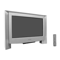
Do you have a question about the Sony FD Triniton KV-32FQ75B and is the answer not in the manual?
Step-by-step guide on tuning television channels using the TV's interface.
Comprehensive guide to the NexTView electronic program guide features and settings.
Locating and tuning video channels, typically for VCRs or external devices.
Accessing detailed program information and setting timers or recordings.
Guide to using the Teletext service, including switching on/off and page selection.
Adjusting the electron beam and Y-splitting axis for optimal picture alignment.
Procedures for achieving screen center convergence using magnets.
Adjusting the focus control for clear picture display.
Adjusting G2 control and white balance settings for optimal picture.
Instructions for safely removing the rear cover and disconnecting speaker cables.
Procedures for removing and reinstalling the TV chassis.
Step-by-step guides for removing various boards (D1, J, B3, F3, H6, H5).
Procedure for removing the picture tube, including anode cap handling.
Proper techniques for handling and removing the anode cap to prevent damage.
Service adjustments using the remote commander RM-893.
Steps to access the TV's service menu for adjustments.
Overview of various test modes and functions accessible via the TEST button.
Visual representation of the TV's internal circuitry and signal flow.
Diagram showing the physical placement of various circuit boards within the TV.
Key for understanding symbols, notations, and component markings in diagrams.
Illustrated breakdown of the TV's chassis components with part numbers.
Exploded view and parts list for the picture tube assembly.
Listing of general parts, accessories, and packaging materials.
Details on supplied accessories and materials for packaging.
Information about the TRACE tool for TV repair assistance and its features.



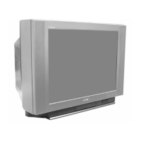
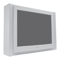
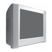
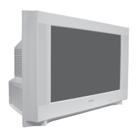
 Loading...