Do you have a question about the Sony KV-PF21N70 and is the answer not in the manual?
Explains STANDBY/TIMER lamp flashes for error diagnosis and probable causes.
Visual representation of flash counts for diagnostic items.
Procedure to stop the flashing indicator lamp by turning off the TV.
How to display and interpret error codes on the TV screen.
Procedures for clearing diagnostic results and quitting the screen.
Overview of the circuit responsible for self-diagnosis functions.
Important safety precautions and warnings for operating the TV.
Guide to initial setup, connecting antenna, and VCR.
Instructions for connecting video equipment like camcorders or game consoles.
Methods to prevent the TV from falling, ensuring stability.
Steps for automatically and manually tuning TV channels.
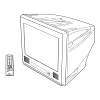
Basic operations for viewing TV, including remote control functions.
Customizing picture and sound settings and modes.
Feature to prevent children from watching specific TV programs.
Quick reference guide for common connection and signal issues.
Troubleshooting steps tailored for different TV models.
Detailed solutions for various picture and sound problems.
Steps to remove the TV's rear cover for access.
Procedure for removing the main chassis assembly.
Instructions for removing the F bracket.
How to place the TV in a service-friendly position.
Procedures for replacing internal components like buttons.
Steps to remove the terminal bracket.
Procedure for removing the degauss coil.
Instructions for safely removing the picture tube.
Procedures for removing and safely handling the anode cap.
Adjusting beam landing using pattern generator and degausser.
Adjusting static, dynamic, and screen-corner convergence.
Adjusting the focus control on the flyback transformer.
Adjusting G2, white balance, and sub-bright settings.
Procedures for entering service mode and making adjustments.
General method for selecting and adjusting items via commander.
Adjusting sub-color, sub-hue, and bell filter settings.
Procedures for initializing and adjusting the A board after memory IC replacement.
Adjusting various parameters to correct picture distortion.
Overall system block diagram of the TV.
Simplified schematic showing major functional blocks.
Diagram showing the physical placement of circuit boards.
Detailed schematics and PWB layouts for various sections.
Illustrations of critical waveforms on the A board.
List and images of diodes, transistors, and ICs used.
Exploded diagram of the TV chassis with part numbers.
Comprehensive list of electronic components and their part numbers.
List of included accessories and packing items.