Do you have a question about the Sony M-909 and is the answer not in the manual?
| Brand | Sony |
|---|---|
| Model | M-909 |
| Category | Microcassette Recorder |
| Language | English |
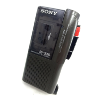
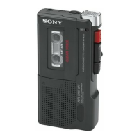
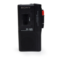
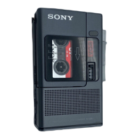
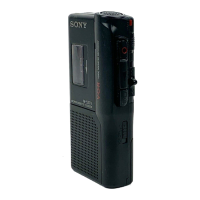
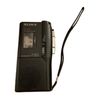
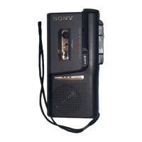
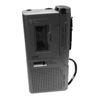
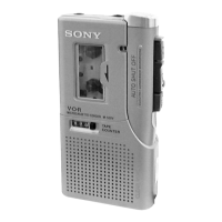
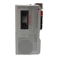
Identifies all external controls and features of the M-909 unit.
Lists important warnings for cassette tape usage and device location.
Details the correct procedure for inserting a battery and notes on battery care.
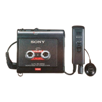
Guides selection of microphones for different recording scenarios and connection methods.
Explains the VOR function for automatic tape-saving recording.
Details microphone sensitivity settings for various sound environments.
Explains tape speed selection for normal vs. extended recording.
Outlines the procedure for removing the front panel assembly and related parts.
Details the removal of the audio board and associated components like the motor.
Describes the disassembly of the head and pinch lever assembly.
Lists essential precautions before performing mechanical adjustments.
Provides specifications and methods for measuring tape torque.
Provides specifications and methods for measuring tape tension.
Defines the standard input signal levels and impedance.
Defines the standard output signal levels and load impedance.
Lists test tape types and their usage for adjustments.
Details the procedure for adjusting the head azimuth using a test tape.
Presents block diagrams for IC401 (TB2001FN) and IC601 (TLP326).