EasyManua.ls Logo

Sony MDR-RF815R - User Manual

Sony MDR-RF815R
22 pages
Print Icon
To Next Page IconTo Next Page
Loading...
MDR-RF815R
AEP Model
UK Model
SERVICE MANUAL
HEADPHONES
Headphones MDR-RF815R
Transmitter TMR-RF815R
MDR-RF815R is the component model block one in the MDR-RF815RK.
COMPONENT MODEL NAME FOR MDR-RF815RK
SPECIFICATIONS
Headphones
Power source DC 2.4 V: Built-in rechargeable
battery
Mass Approx. 240 g (8.1 oz.) incl.
built-in rechargeable battery
Built-in Ni-Cd rechargeable battery
Model name NC-AA
Voltage 1.2 V
Capacity 700 mAh
Design and specifications are subject to change without
notice.
Ver 1.0 2000. 06
Question and Answer IconNeed help?

Do you have a question about the Sony MDR-RF815R and is the answer not in the manual?

Summary

Headphones Specifications

Power Source and Mass

Specifies DC 2.4V power source and approximate mass of 240g.

Built-in Battery Details

Details the Ni-Cd rechargeable battery: NC-AA, 1.2V, 700mAh.

General Operation and Safety

Operating Instructions

Using volume, tuning, and auto power off features.

Service Safety Checks

Pre-service checks on connections, parts, voltage, and repair guidelines.

RX-Base Board Disassembly

Board Removal and Wire Soldering

Procedure for removing the RX-BASE board and precautions for wire soldering.

Lead Wire Routing

Wire Management for Hangers

Illustrated guide for routing lead wires on Cover (L) and Cover (R) hangers.

Electrical Adjustments

Frequency Checks and Adjustments

Adjusting free-run and receive frequencies for the headphones.

Modulation and Separation Tests

Checking carrier modulation and L/R channel separation.

RX-Base Board Adjustment Locations

Component Side Diagram

Diagram showing adjustment points on the component side of the RX-BASE board.

System Diagrams

Headphones and Transmitter Block Diagrams

Schematics showing functional blocks of both headphones and transmitter.

Schematic Diagrams

RX-Base Board Circuit Schematic

Detailed circuit schematic for the RX-BASE board.

Printed Wiring Boards

RX-Base Board Layouts

Component layout for the RX-BASE board, showing both sides.

Headphones Parts and Views

RX-Base Board Exploded View

Diagram of assembly of the RX-BASE board and its components.

RX-Base Electrical Parts List

List of electrical components for the RX-BASE board.

RX-Base Electrical Parts Details

Resistors, Transistors, and Coils

List of resistors, transistors, and coils for the RX-BASE board.

Variable Resistors and Switches

List of variable resistors, switches, and vibrator for the RX-BASE board.

Transmitter Specifications

General Transmitter Specifications

Carrier frequency, channel, modulation, and frequency response of the transmitter.

Transmitter Power, Input, and Dimensions

Details on power source, audio input, dimensions, and mass.

Transmitter Setup and Safety

Transmitter Connection Guide

Instructions for connecting the transmitter to audio/video sources.

Transmitter Service Safety Checks

Pre-service and post-repair checks for the transmitter.

Transmitter Disassembly

Cabinet and TX-Base Board Removal

Procedures for disassembling the transmitter's upper cabinet and TX-BASE board.

Transmitter Electrical Adjustments

Pilot Signal and Frequency Adjustments

Adjusting pilot signal modulation and transmitter frequencies.

Transmitter Block Diagram

TMR-RF815 R System Overview Diagram

Block diagram illustrating the TMR-RF815R transmitter system.

Transmitter Schematic Diagram

TX-Base Board Circuit Schematic

Detailed circuit schematic for the TX-BASE board.

Transmitter Printed Wiring Board

TX-Base Board Component Layout

Component layout of the TX-BASE board.

Transmitter Parts and Views

TX-Base Board Exploded View

Diagram of assembly of the TX-BASE board and its components.

TX-Base Electrical Parts List

List of electrical components for the TX-BASE board.

Transmitter Electrical Parts Details

Coils, Transistors, Resistors, and Switches

List of various electronic components for the TX-BASE board.

Overview

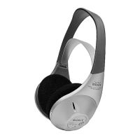
This document serves as a service manual for the MDR-RF815R headphones and its accompanying transmitter, the TMR-RF815R, which together form the MDR-RF815RK wireless headphone system. It covers both AEP and UK models.

Function Description

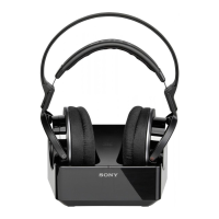
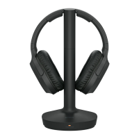
The MDR-RF815R is a pair of wireless headphones designed for audio reception from a dedicated transmitter, the TMR-RF815R. The system allows users to enjoy audio without the constraints of cables, making it suitable for use with various audio/video equipment such as CD Walkman, MD Walkman, WALKMAN, VCR, etc. The headphones feature an auto power on/off function that automatically turns off the power when removed from the head, conserving battery life.

The TMR-RF815R transmitter is responsible for broadcasting audio signals to the headphones. It supports three selectable channels (Ch1, Ch2, Ch3) and uses FM stereo modulation. The transmitter connects to audio/video equipment via phono jacks or a stereo mini jack, offering flexibility in source connection. It is powered by a DC 9V AC power adaptor.

Important Technical Specifications

Headphones (MDR-RF815R)

  • Power source: DC 2.4 V, supplied by a built-in rechargeable battery.
  • Mass: Approximately 240 g (8.1 oz.), including the built-in rechargeable battery.
  • Built-in Ni-Cd rechargeable battery:
    • Model name: NC-AA
    • Voltage: 1.2 V
    • Capacity: 700 mAh

Transmitter (TMR-RF815R)

  • Carrier frequency: 863.5 – 864.5 MHz.
  • Channel: Ch1, Ch2, Ch3.
  • Modulation: FM stereo.
  • Frequency response: 20 – 20,000 Hz.
  • Power source: DC 9 V, supplied by an AC power adaptor.
  • Audio input: Phono jacks/stereo mini jack.
  • Dimensions: Approximately 150 mm diameter × 108 mm (6 x 4 1/3 in.) (w/h).
  • Mass: Approximately 190 g (6.2 oz.).

Usage Features

Setting up the Transmitter

  1. Connect to audio/video equipment: The transmitter can be connected to various audio/video sources. Users should select the appropriate hookup based on the jack type of their equipment. Options include phono jacks (red for right channel, white for left channel) or a stereo mini jack using the supplied connecting cord and unimatch plug adaptor.
  2. Power: The transmitter is powered by a DC 9V AC power adaptor.
  3. Noise Filter: A noise filter switch (S401) is available to turn the noise filter ON or OFF.
  4. Channel Selection: A channel switch (S402) allows selection between three channels (1, 2, 3) to optimize signal reception and avoid interference.

Using the Headphones

  1. Volume Control: The headphones are equipped with a VOL control to adjust the audio volume to a moderate level.
  2. Tuning Control: A TUNING control allows users to tune the headphones to the frequency of the transmitter until the audio signal is clear.
  3. Auto Power On/Off Function: When the headphones are removed from the head, the power automatically turns off. To ensure this function works correctly, the self-adjusting band should not be pulled up, as this would keep the headphones switched on. The power turns on automatically when the headphones are placed on the head.

Maintenance Features

The service manual provides detailed instructions for disassembly, electrical adjustments, and safety check-out procedures, intended for qualified service personnel.

Disassembly

The manual outlines step-by-step disassembly procedures for both the headphones (RX-BASE BOARD) and the transmitter (CABINET (UPPER), TX-BASE BOARD). This includes:

  • Headphones:
    • Removing four screws and the cover (R) hanger.
    • Removing the push switch (1 key).
    • Desoldering two connections and nine connections to access the RX-BASE board.
    • Detailed instructions for setting lead wires, ensuring correct routing and soldering positions, with specific wire numbers (e.201, No.202, No.203, No.204, No.205) and corresponding colors (green, red, black).
    • Precaution for installation of the suspender and push switch.
  • Transmitter:
    • Removing the upper cabinet by first removing four screws.
    • Accessing the TX-BASE board by lifting the cabinet assembly (lower).

Electrical Adjustments

The manual details several electrical adjustment procedures for both the headphones and the transmitter to ensure optimal performance:

  • Headphones (RX-BASE BOARD):
    • Free run frequency check and adjustment: Involves setting the transmitter to no signal, checking the power indicator, setting the transmitter channel to 1, setting headphone tuning to center, connecting a frequency counter to IC301 pin 4 and GND, and adjusting RV301 to achieve a specified frequency of 76kHz ± 50Hz.
    • Receive frequency check and adjustment: Involves setting the transmitter channel to 2, noise filter to OFF, inputting a 1kHz, 316mVrms signal to the transmitter, maintaining a 5-meter distance between transmitter and headphones, setting headphone volume to minimum, tuning to center, connecting an oscilloscope to IC301 pins 6 and 4, checking waveform, and adjusting coil L301 if necessary.
    • Carrier modulation check: Involves setting the transmitter channel to 2, noise filter to OFF, inputting a 1kHz, 316mVrms signal, adjusting headphone tuning (RV303), setting volume to minimum, connecting an oscilloscope to IC301 pins 6 and 4, checking waveform, connecting an AC volt meter, and verifying the AC volt meter reading to 26mVrms ± 2mV.
    • Separation check: Similar to carrier modulation check but focuses on measuring AC voltage at speaker terminals (L+,L- and R+,R-) and ensuring a difference of more than 20dB between L and R channels.
  • Transmitter (TX-BASE BOARD):
    • Pilot signal Modulation Check and Adjustment: Involves setting the channel to CH2, ensuring no signal input, measuring the movable terminal of RV403 with a digital voltmeter (AC range), and adjusting RV403 to achieve 1.6mVrms ± 0.1mV.
    • Send Frequency Check: Involves setting the noise filter switch to OFF, inputting a 1kHz, 40mVrms signal to L-CH (J402), connecting a telescopic antenna to a frequency counter, and measuring the frequencies of CH1, CH2, and CH3 to ensure they meet specifications (CH1: 863.5 MHz ± 40 kHz, CH2: 864.0 MHz ± 40 kHz, CH3: 864.5 MHz ± 40 kHz). If not, the VCO unit may need to be exchanged.

Safety Check-Out

After any repair, a safety check-out procedure must be performed before returning the device to the customer. This includes:

  • Checking for unsoldered or poorly-soldered connections, solder splashes, and bridges on the board.
  • Ensuring interboard wiring is not "pinched" or contacting high-wattage resistors.
  • Looking for unauthorized replacement parts, especially transistors, and recommending their replacement.
  • Identifying parts showing obvious signs of deterioration and recommending their replacement.
  • Checking B+ voltage against specified values.
  • Flexible Circuit Board Repairing: Specific precautions for soldering, such as maintaining soldering iron temperature around 270°C, avoiding touching the same conductor more than three times, and not applying force on the conductor.

The manual also includes detailed exploded views and electrical parts lists for both the headphones and the transmitter, providing part numbers and descriptions for all components.

Sony MDR-RF815R Specifications

General IconGeneral
BrandSony
ModelMDR-RF815R
CategoryWireless Headphones
LanguageEnglish

Related product manuals