Cautions
Be
sure to install this unit in the dashboard
of
the car
as
the rear side
of
the unit becomes
hot
during use.
• This unit
is
designed for negative ground (earth)
12
V
DC operation only.
•
Do not get the leads
under
a screw,
or
caught in moving
parts (e.g. seat railing).
•
Before making connections,
turn
the car ignition off to
avoid short circuits.
• Connect the
yellow
and
red
power supply leads only
after all other leads have been connected.
•
Run
all ground (earth)
leads
to
a common ground
(earth) point.
•
Be
sure to insulate any loose unconnected leads with
electrical tape for safety.
• The use
of
optical instruments with this product
will
increase eye hazard.
Notes on
the
power
supply lead (yellow)
•
When connecting this unit in combination with other
stereo components, the connected car
circuit's rating
must be higher than the sum
of
each
component's
fuse.
•
When
no car circuits are rated high enough, connect
the unit directly to the battery.
Parts list
[]
•
The numbers in the list are keyed to those in the
instructions.
•
The bracket
CD
and the protection collar
@
are
attached to the unit before
sh~ping.
Before mounting
the unit, use the release keys
@
to remove the bracket
CD
from the unit. For details, see
"Removing
the
protection collar and the bracket
(IJ)"
on
the reverse
side
of
the sheet.
•
Keep
the
release
keys
®
for
future
use
as
they
are
also
necessary
if
you remove
the
unit
from your
car.
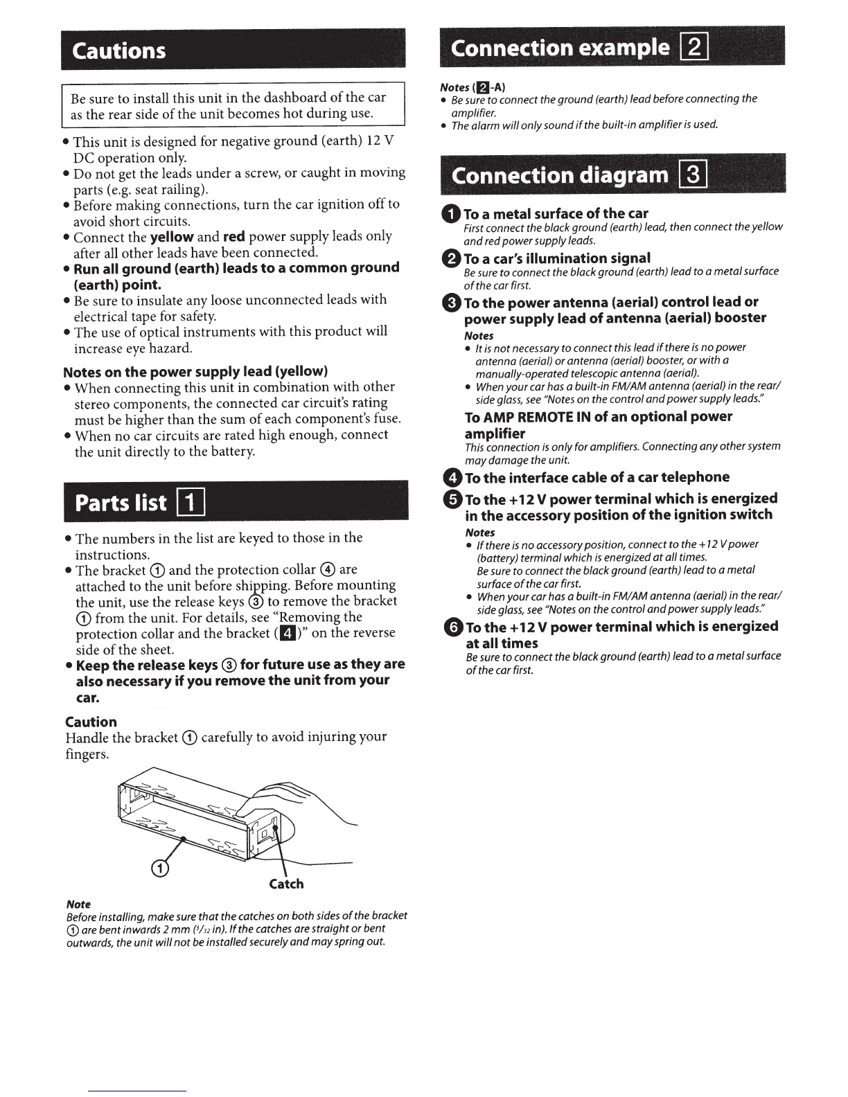
Caution
Handle the bracket
CD
carefully to avoid injuring your
fingers.
Catch
Note
Before installing, make sure
that
the catches on
both
sides
of
the bracket
CD
are
bent
inwards 2
mm
{3/32
in).
If
the catches are
straight
or
bent
outwards, the
unit
will
not
be installed securely
and
may
spring out.
Connection example
[]]
Notes(lfi-A)
•
Be
sure
to
connect the
ground
(earth) lead before connecting the
amplifier.
•
The
alarm
will
only
sound
if
the built-in
amplifier
is
used.
Connection diagram
~
0
To
a
metal surface
of
the
car
First connect the black
ground
(earth) lead, then connect the
yellow
and
red
power
supply leads.
8
To
a car's illumination signal
Be
sure
to
connect the black
ground
(earth) lead to a
metal
surface
of
the car first.
E)
To
the
power antenna
(aerial) control lead
or
power
supply lead
of
antenna
(aerial)
booster
Notes
•
It
is
not
necessary
to
connect this lead
if
there
is
no
power
antenna
(aerial)
or
antenna
(aerial) booster,
or
with
a
manually-operated telescopic
antenna
(aerial).
•
When
your
car has a built-in FM/AM
antenna
(aerial) in the
rear/
side glass,
see
"Notes
on the control
and
power
supply leads."
To
AMP REMOTE IN
of
an
optional power
amplifier
This
connection
is
only
for
amplifiers. Connecting
any
other
system
may
damage
the unit.
0
To
the
interface
cable
of
a car
telephone
e
To
the
+
12
V
power
terminal
which
is
energized
in
the
accessory position
of
the
ignition switch
Notes
•
If
there
is
no
accessory position, connect
to
the
+
12
V
power
(battery)
terminal
which
is
energized
at
all
times.
Be
sure
to
connect the black
ground
(earth) lead
to
a
metal
surface
of
the car first.
•
When
your
car has a built-in FM/AM
antenna
(aerial) in the
rear/
side glass,
see
"Notes on the control
and
power
supply leads."
0
To
the
+
12
V
power
terminal which
is
energized
at
all times
Be
sure
to
connect the black
ground
(earth) lead
to
a
metal
surface
of
the car first.