Do you have a question about the Sony MHC-881 and is the answer not in the manual?
Procedures for measuring AC leakage current from exposed metal parts to earth ground.
Guidelines for safely handling the optical pick-up and its flexible board to prevent damage.
Instructions for safely checking the laser diode emission, emphasizing distance from the objective lens.
Step-by-step procedure for removing the front panel, including component references.
Procedure for removing the CD block mechanism from the unit.
Steps for disassembling the cassette, mechanism deck, and HP/MIC board.
Procedures for mechanical adjustments, including torque and tape tension measurements.
Guidelines for electrical adjustments in the deck section, including switch positions and test modes.
Adjustment procedure for focus bias when the optical block is replaced, focusing on eye pattern.
| Brand | Sony |
|---|---|
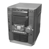
| Model | MHC-881 |
| Category | Hi Fi Component |
| Language | English |