EasyManua.ls Logo

Sony MHC-D7 - Page 21

Sony MHC-D7
85 pages
Print Icon
To Next Page IconTo Next Page
To Previous Page IconTo Previous Page
Loading...
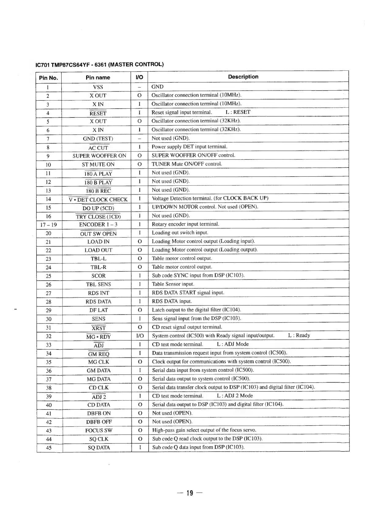
IC701
TMP87CS64YF
-
6361
(MASTER
CONTROL)
Pin
No.
}
Pin
name
VO
Description
be]
VSS
—
|
GND
2
X
OUT
Oo
Oscillator
connection
terminal
(]OMHz).
3
XIN
e
I
l
Oscillator
connection
terminal
(1OMHz).
4
RESET
I
Reset
signal
input
terminal.
L:
RESET
|
5
X
OUT
Oo
Oscillator
connection
terminal
(32KHz).
=
6
XIN
I
Oscillator
connection
terminal
(32KHz).
F
7
GND
(TEST)
-
Not
used
(GND).
8
AC
CUT.
a
Power
supply
DET
input
terminal.
9
SUPER
WOOFFER
ON
O
|
SUPER
WOOFFER
ON/OFF
control.
10
ST
MUTE
ON
O
|
TUNER
Mute
ON/OFF
control.
i
[ul
180A
PLAY
I
|
Notused
(GND).
12
180
B
PLAY
I
Not
used
(GND).
13
180
B
REC
I
Not
used
(GND).
14
V
¢
DET
CLOCK
CHECK
I
Voltage
Detection
terminal.
(for
CLOCK
BACK
UP)
15
DO
UP
(5CD)
1
|
UP/DOWN
MOTOR
control.
Not
used
(OPEN).
:
16
TRY
CLOSE
(1CD)
I
|
Not
used
(GND).
I
Rotary
encoder
input
terminal.
I
Loading
out
switch
input.
21
LOAD
IN
O
|
Loading
Motor
control
output
(Loading
input).
22
LOAD
OUT
oO
Loading
Motor
control
output
(Loading
output).
24
TBL-R
O
|
Table
motor
control
output.
25
SCOR
ne
Sub
code
SYNC
input
from
DSP
(IC103).
26
TBL
SENS
ae
Table
Sensor
input
27
RDS
INT
I
RDS
DATA
START
signal
input.
28
RDS
DATA
sais
I
ah
RDS
DATA
input.
29
DF
LAT
oO
|
Latch
output
to
the
digital
filter
(IC
104).
30
SENS
I
Sens
signal
input
from
the
DSP
(IC103).
31
ce
XRST
O
|
CDreset
signal
output
terminal.
32
MG
«
RDY
I/O
|
System
control
(C500)
with
Ready
signal
input/output.
L
:
Ready
|
33
ADI
1
|
CDtest
modeterminal.
|
L:
ADJ
Mode
|
34
GM
REQ
I
Data
transmission
request
input
from
system
control
(IC500).
35
MG
CLK
oO
Clock
output
for
communications
with
system
control
(IC500).
36
GM
DATA
I
Serial
data
input
from
system
control
(IC500).
7
37
MG
DATA
O
Serial
data
output
to
system
control
(IC500).
38
CD
CLK
O
|
Serial
data
transfer
clock
output
to
DSP
(fC103)
and
digital
filter
(C104).
39
ADJ
2
1
|
CDtest
mode
terminal.
L
:
ADJ
2
Mode
40
CD
DATA
oO
Serial
data
output
to
DSP
(1C103)
and
digital
filter
(IC104).
41
DBFB
ON
O
|
Not
used
(OPEN).
[42
=
DBFB
OFF
Not
used
(OPEN).
7
43
FOCUS
SW
High-pass
gain
select
output
of
the
focus
servo.
SQ
CLK
SQ
DATA
Sub
code
Q
read
clock
output
to
the
DSP
(IC
103).
Sub
code
Q
data
input
from
DSP
(IC
103).