Do you have a question about the Sony MHC-DX30 and is the answer not in the manual?
Details power output, distortion, and CD player specifications.
Outlines safety checks, AC leakage testing, and component warnings.
Notes on handling optical pick-up and laser diode emission.
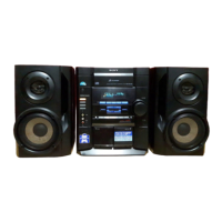
Shows remote layout and provides instructions for setting the system time.
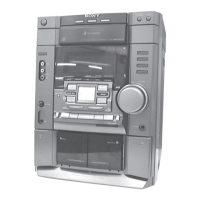
Details the steps for disassembling the unit, starting with the top case.
Explains CD door and front panel section removal processes.
Explains removal of key, sub trans, trans, sensor, and video out boards.
Details removal of main board, power board, and base unit assembly.
Covers basic test modes for resetting and operational checks.
Details advanced test modes for tuner, system checks, and version display.
Explains aging mode for operational checks and its error display system.
Describes aging mode sequences and function input selection.
Covers adjustments for CD section, S-curve, and RF level checks.
Details procedures for checking E-F balance and RF PLL frequency.
Illustrates the block diagram for the tuner and CD sections.
| Type | Mini Hi-Fi System |
|---|---|
| CD Player | Yes |
| Radio Tuner | FM/AM |
| Bluetooth | No |
| USB Playback | No |
| CD Player Type | Single Disc |
| Remote Control | Yes |
| CD Playback | Yes |
| Functions | CD, Radio |
| Output Power | 30W per channel (at 6 ohms, 1kHz, 10% THD) |
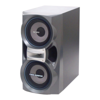
| Speakers | 2 Speakers |