EasyManua.ls Logo

Sony MHC-DX50 Service Manual

Sony MHC-DX50
76 pages
To Next Page IconTo Next Page
Page #1 background imageLoading...
Page #1 background image
MHC-DX50/RG80
Canadian Model
MHC-RG80
Australian Model
E Model
MHC-DX50
SERVICE MANUAL
MINI Hi-Fi COMPONENT SYSTEM
Sony Corporation
Audio Entertainment Group
General Engineering Dept.
Ver 1.0 2001. 02
9-929-588-11
2001B1600-1
© 2001.2
COMPONENT MODEL NAME
MHC-DX50/RG80 are composed of following models.
As for the service manual, it is issued for each component model,
then, please refer to them.
REAR SPEAKER
SYSTEM
COMPACT DISC DECK
RECEIVER SYSTEM
FRONT SPEAKER
SYSTEM
PARTS LIST
Part No. Description Remark
ACCESSORIES & PACKING MATERIALS
********************************
1-476-503-11 REMOTE COMNDUDER (RM-SR210)
1-501-374-11 ANTENNA, LOOP
1-501-659-71 ANTENNA, (FM)
4-210-254-41 CUSHION (FOOT)
4-223-953-01 COVER, BATTERY (FOR RM-SR210)
4-232-650-11 INSTRUCTION MANUAL (
DX50 : AUS, E2, E51, MX,SP/RG80)
(ENGLISH)
4-232-650-21 INSTRUCTION MANUAL
(DX50 : E2, SP/RG80)(FRENCH)
4-232-650-31 INSTRUCTION MANUAL
(DX50 : E2, E51, MX, SP)(SPANISH)
4-232-650-41 INSTRUCTION MANUAL
(DX50 : SP)(CHINESE)
4-232-650-71 INSTRUCTION MANUAL
(DX50 : KR)(KOREAN)
MHC-RG80
HCD-RG80
SS-DX50
SS-RS50
MHC-DX50
HCD-DX50
SS-DX50
Abbreviation
E2 : 120 V AC Area in E model
E51 : Chilean and peruvian model
SP : Singapore model
MX : Mexican model
AUS : Australian model
KR : Korea model
SPECIFICATIONS

Other manuals for Sony MHC-DX50

Question and Answer IconNeed help?

Do you have a question about the Sony MHC-DX50 and is the answer not in the manual?

Sony MHC-DX50 Specifications

General IconGeneral
TypeMini Hi-Fi System
Speaker Configuration2.0
CD PlayerYes
FM RadioYes
BluetoothNo
USB PlaybackYes
TunerFM
Speakers2
FunctionsCD, FM Radio
Power Output100W Total Power (50W per channel)

Summary

Component Identification

Component Model Names

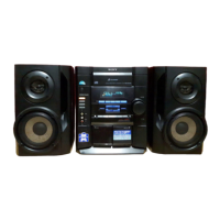
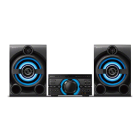
Lists the specific models for each component in the system.

System Specifications

Covers general, amplifier, CD, tape, and tuner specifications.

Safety and Handling Precautions

Optical Pick-Up Handling Notes

Guidance on handling the optical pick-up to prevent damage.

Safety Check-Out and Leakage

Procedures for safety checks and AC leakage measurement.

General Information and Controls

Main Unit Parts Identification

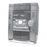
Identifies major parts of the main unit.

Remote Control Overview

Identifies parts and describes buttons on the remote control.

Setting Time and Power Modes

Instructions for setting the clock and using power saving mode.

Disassembly Procedures

Unit Disassembly Steps

Step-by-step guide for disassembling the main unit and its boards.

Test Modes

System Test Modes

Details various test modes like reset, tuner step, GC, and MC tests.

Adjustments

Mechanical Adjustments

Covers torque measurement and head azimuth adjustment.

Electrical Adjustments

Details tape speed, playback level, and REC adjustments.

Diagrams and IC Information

Circuit Board Locations and Diagrams

Shows board layouts, block diagrams, and schematics.

IC Pin Function Descriptions

Details pin functions for key integrated circuits.

IC Block Diagrams

Illustrates the internal structure of major ICs.

Exploded Views

Unit Exploded Views

Provides exploded views and parts lists for various unit sections.

Electrical Parts List

Electrical Parts by Section

Comprehensive list of electrical parts categorized by board/section.

Speaker System Manual

Speaker System Specifications

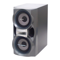
Details speaker system type, units, impedance, and dimensions.

Speaker Exploded View and Parts List

Exploded view and parts list for the speaker system.

Related product manuals