EasyManua.ls Logo

Sony MHC-D7 - Page 41

Sony MHC-D7
85 pages
Print Icon
To Next Page IconTo Next Page
To Previous Page IconTo Previous Page
Loading...
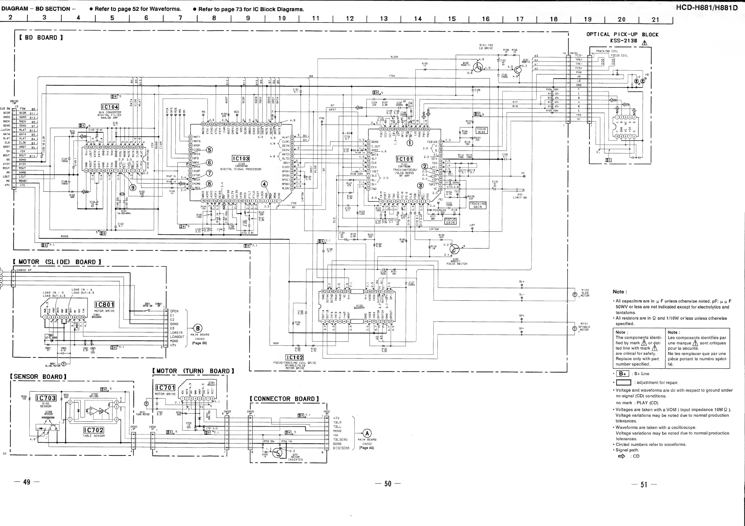
HCD-H881/H881D
DIAGRAM
—
BD
SECTION
—
@
Refer
to
page
52
for
Waveforms.
@
Refer
to
page
73
for
IC
Block
Diagrams.
!
OPTICAL
PICK-UP
BLOCK
[
BD
BOARD
}
KSS-213B
4
101,
102
a
LO
BRIVE
I
Rigs
R192
TRACKING
COIL
+
WW
oe
es
”
FOCUS
COIL
XLON
{
&
AS
Bi
To
4.9
Scior
gio!
Ad
TRK+
a102
T
47
MSB710
|
TRK-
o
ae
MUNZI11
re
Wo
ip
02
Al
of
i
:
AZ St
‘
a
t—+©)
a
me
FSW
T
fad
4.9
Pe
ce
LO
bg
(
aaa
ae
ieee
12]
@@
a
a
a
a
ol__one__
Tt
=
ime
cigs
R104
100k
Lo
F
ly
RIQS
47k
C.
+f
{
.
o
[Bas
&
« °
Ty
if
a
R106
47k
||
B
alwle
8
So
g
1}
o o
cng
abel
a
a)
|B
AC
aga
a
alol=
RE
B+O
riog
47m
|
|
8
B/A_CONVERTER
Wo
be
‘
scor
|
{
scor_pit
DIGITAL
FILTER
99900
ae
[of
sy
soso
||
{
soso
pio
ANALOG
AMP
FOK
lve
sack
g
ed
1 1
SENS
.
LATCH
BATA
leet
XLAT
%
iS
ENT
0.1
1
~o
al=
MNTS.
1
CLK
S
a/2|5
Gs)
xROF
Ise
3
XRST
0
+1B1G
C125
+
a
(29)
c2Po
SV
be
2
6.01
B.
b
=
Gay
ase
clos
BOUT
BY
=
0.7
Ae
é
(2?)
GFS
——
a)
ASSV
3
(26)
88
16103
1C10)
(25)
CX®2507AG
blz
CXA1782B0
1
ROUT
=
_|
Ga)
xucF
AIGITAL
SIGNAL
PROCESSOR
e£lS|
je
TRACKING
FOCUS/
AG
5
EIR
/SLED
SERVO
vc
LouT
Rua7
1k]
9.4
(28)
GTOP
5
$5137
RF
AMP
——+-
o
MG
aaa
ye
i
q
cis
Ss3(11)
PCMA
47
+7V
ro
al
{we
M7 ae
\
creme
1
1k
a
S101
¢
5
8
LIMIT
SW
x
a
I
E
FOK
'
TRAGeIN
Go
oa
RF
{
4
x10!
ai
16.9344MHz
i
“7
Te
>
I!
o
mS}
[Sls
ue
a
agen
oye
g
|e)
[els
Ters
im
ols
10.7
[B+]"5
;
al
=
LMTSW
2
I
7
oo
ine
5“
0
C124
Bt
R125
ms
(B+)
a
OBB
ue
Wie
az
|
Ae
|
Bes
AYNS
2
0
L429
+
(Of
ie
2.4
:
hs
FOCUS
SWITCH
MOTOR
(SLIDE)
BOARD
I
en
ag
a
a
nnn
oss
J
SL+
:
|
LOAD
IN:
&
I
:
alee
Note
:
:
SLEO
:
LOAD
OUT:0.3
we
®
4
MOTOR
3
¢
-
All
capacitors
are
in
ys
F
unless
otherwise
noted.
pF:
uy uw
F
$801
. .
.
open
sy
OP
1
50WV
or
less
are
not
indicated
except
for
electrolytics
and
1
MOTOR
BRIVE
OPEN
tantalums.
1C801
SP+
.
*
.
BABZBEN
|
ep
9
-
All
resistors
are
in
Q
and
1/10W
or
less
unless
otherwise
EC
vf
Miot
specified.
ome
SPINOLE
E3
@®
Mnarar
LOABIN
!
g
:
Note:
Note
:
!
LOABOUT
ipeheccatad
The
components
identi-
|
Les
composants
identifiés
par
ie
(Page
39)
map
fied
by
mark
ordot-
|
une
marque
/f\
sont
critiques
ted
line
with
mark
pour
la
sécurité.
are
critical
for
safety.
Ne
les
remplacer
que
par
une
——_
!
I
Replace
only
with
part
piéce
portant
le
numéro
spéci-
FOCUS/TRACKING
COIL
BRIVE
ifi
i
RANG
co
number
specified.
fié.
MOTOR
BRIVE
.
[B+
|
:
B+
Line
.
C_]
:
adjustment
for
repair.
{MOTOR
(TURN)
BOARD)
a
eae
[SENSOR
BOARD
]
2
54641
|
BH,
©
!
1C701
oP
2
iy
=
8
-
Voltage
and
waveforms
are
dc
with
respect
to
ground
under
Bsizeez
as
:
ae
R701
ic702,
MOTOR
RIVE
I
no-signal
(CD)
conditions.
R702
(1C703]
e20
RPI1391
A
ee
is
a
|
1
PODPODOD,
|
[CONNECTOR
BOARD]
|
etnaiee
ERY
(eb)
;
[r
;
SENEOR
>
>
©
i]
:
1
T
0
po
—
es
caves
I
*
Voltages
are
taken
with
a
VOM
(
Input
impedance
10M
).
ois
TaN
oro
|
Byer
ee
s
ae
fap
BAz:!
1
Voltage
variations
may
be
noted
due
to
normal
production
CLLLILRLIZIZA
x
2
°
+7V
2
Y
o
|
|
c702
lo
Lo
foetal
TBLR
tolerances.
!
cN705
cN706
Wy
°
TBLL
+
Waveforms
are
taken
with
a
oscilloscope.
1C702
rk
gE
aside
i
-
MGN
F
LA
i
I]
HY
|
me
iB
Voltage
variations
may
be
noted
due
to
normal
production
4.8
ay
|
Sar
EsPeNeoe
Lo
|
|
I
rl
TBLSENS
MAIN
BOARD
tolerances.
a
I
ml
CI
Pa
ee
CN202,
*
Circled
numbers
refer
to
waveforms.
eal
1
mal
at
cay
oF
[oy]
BISCSENS
(Page
40)
+
Signal
path.
4
4
1
8 8
02
2S
=
ea
70s
i)
|
a8
wp
:CD
INVERTER
—
90
—
coat
ie