7
GB
Overview
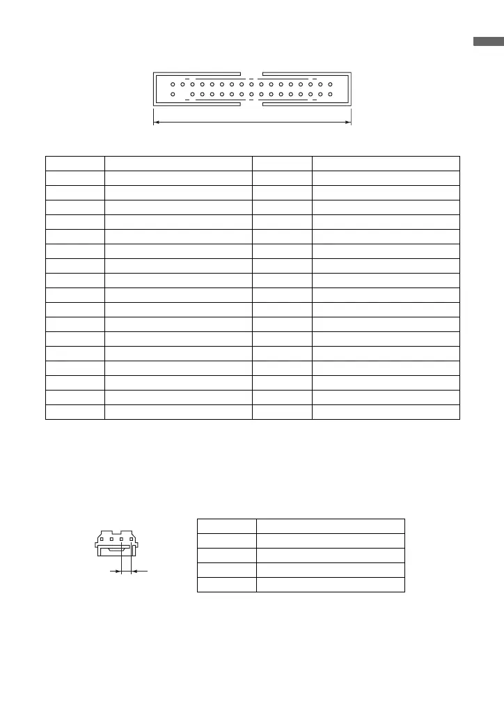
FDD Interface Connector Pin Assignments
*1
Pin #3 of the FDD interface connector is physically removed because of the presence
of a keying plug on certain connectors (used to prevent incorrect connection).
*2
The drive selection is fixed to 1.
Power Connector Pin Assignments
(EI Connector)
13 3132
24 32
34
48.4 mm (1.91 in.)
Pin No. Signal Pin No. Signal
1 Not connected 2 Not connected
3Key
*1
4 Not connected
5 Ground 6 Not connected
7 Ground 8 INDEX
9 Ground 10 Not connected
11 Ground 12 DRIVE SELECT 1
*2
13 Ground 14 Not connected
15 Ground 16 MOTOR ON
17 Ground 18 DIRECTION
19 Ground 20 STEP
21 Ground 22 WRITE DATA
23 Ground 24 WRITE GATE
25 Ground 26 TRACK 00
27 Ground 28 WRITE PROTECT
29 Ground 30 READ DATA
31 Ground 32 HEAD 1 SELECT
33 Ground 34 DISK CHANGE
2.5 mm (0.01 in.)
Pin No. Signal
1+5 V
2Ground
3Ground
4 Not connected
1234
 Loading...