Do you have a question about the Sony MU-R201 and is the answer not in the manual?
Newly developed 2-channel audio processing LSI creates high-quality stereo effects.
100 factory presets selected by professionals for various applications.
EDIT and EQ functions allow modification of presets and user memory storage.
10 basic modes with versatile effects like hall ambience and multi-gate reverb.
Simple and straightforward memory selection and adjustment for live performance.
Two channels can operate separately, allowing use with different instruments.
Up to 26 parameters can be set to design exact sound fields and special effects.
Programmable two-channel, four-band equalizer with adjustable parameters.
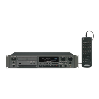
Optional remote control unit and foot switch for convenient operation.
Dual input/output jacks accommodate standard phone or RCA plugs.
Integrated MIDI interface for program change signals and effect level control.
Procedure to check AC leakage from metal parts to earth ground and between parts.
Details the function of front panel controls like power, input, dry, and effect level.
Explains the six functions activated by the function buttons (Memory, Edit, EQ, Write, MIDI).
Describes the action of parameter buttons based on selected functions and color coding.
Function of the bypass switch to toggle signal processing circuits on or off.
Details all rear panel connectors including power, MIDI, remote, and I/O ports.
Important notes regarding making connections, including power off.
Step 1: Power on the MU-R201 and check indicator lights.
Step 2: Activate the preset memory function.
Step 3: Use +/- keys to select the first digit of the desired preset number.
Step 4: Use numeric keys to select the second digit of the preset number.
Step 5: Adjust input and effect/dry signal levels for desired sound.
Presets 00-09 for basic modes, 10-64 for recording/instrument use.
Presets 65-74 for public-address applications and live events.
Presets 75-84 for radio shows/live performances and 85-99 for hall simulation.
Explains sound reflection, decay, and acoustic properties.
Describes direct sound, early reflections, and reverberation components.
How the MU-R201 achieves natural stereo reverberation using digital processing.
Details parameters like E. RFL. T., E. RFL. L., REV. T., PRE. DT, RT HIGH, SPREAD, PHASE, FBL, REPEAT, DEPTH, SPEED.
Parameters for the four-band equalizer (LOW, L MID, H MID, HIGH) and Effect Level (EFF. L.).
Creates spacious reverberation for large halls or open-air settings.
Creates reverberation of small locations like echo rooms or clubs.
Produces plate reverberation, common in studios for vocals and strings.
Used for drum and percussion effects with gate circuit cutoff.
Special effect, gate reverb in reverse, suitable for cymbals.
Provides separate multi-delay in both channels, usable as two delay machines.
Uses delay signal for feedback and auto-panning on the resulting signal.
Separate reverb in both channels, similar to plate reverb.
Channel 1 has reverb (mode 7), channel 2 has gate reverb (mode 3).
Channel 1 has reverb (mode 7), channel 2 has delay (mode 5).
Step 1: Select either Preset Memory or User Memory to recall effects.
Step 2: Use +/- keys to adjust the first digit of the memory number.
Step 3: Use numeric keys to enter the second digit of the memory number.
Step 1: Select the memory number for the effect to be edited.
Step 2: Press the EDIT button to enter the editing mode.
Step 4: Use +/- keys to change parameter values.
Adjust the two-channel, four-band equalizer settings.
Adjust the output level for the effect when the EFFECT control is at maximum.
Feature available in modes 8 and 9 for serial connection of effects.
Step 1: Press the WRITE button to initiate data storage.
Step 2: Select the memory number using +/- and numeric keys.
Step 3: Press WRITE again to confirm and store the data.
How to check and change memory numbers corresponding to MIDI program numbers.
Setting the MU-R201's MIDI channel to match external MIDI equipment.
Using control change signals to adjust effect levels.
Example setup for connecting the MU-R201 for recording purposes.
Example of using the unit as an effecter with mono/stereo input.
Example of using the two channels separately for different instruments.
Setup for connecting to a standard audio system for conventional listening.
Example setup for creating a surround sound experience.
Guidelines for achieving a more present and realistic sound effect.
Instructions for positioning and adjusting speakers for presence effect.
Explains how speaker placement affects sound imaging and presence.
Advice on selecting speakers that complement the main speakers for presence.
Descriptions for presets 00-19, covering standard patterns and recording use.
Details the format for channel voice, channel mode, and system messages.
Specifies format for program change, control change, note on/off messages.
Specifies format for omni mode on/off messages.
Details format for system exclusive messages like data transfer.
Procedure to adjust the unit's offset voltage for stability.
Procedure to adjust the distortion rate to a minimum level.
Diagram showing the placement of components on the chassis.
Details the location of semiconductors on the mounting diagram.
Technical schematic showing the audio signal path and circuitry.
Technical schematic showing the system control and digital circuitry.
Visual breakdown of parts for assembly and replacement.
Visual breakdown of parts for assembly and replacement (continued).
Diagrams showing the pin configurations of various semiconductors.
List of included accessories and packing materials.
| Brand | Sony |
|---|---|
| Model | MU-R201 |
| Category | Recording Equipment |
| Language | English |