EasyManua.ls Logo

Sony RCD-W500C Service Manual

Sony RCD-W500C
114 pages
To Next Page IconTo Next Page
Page #1 background imageLoading...
Page #1 background image
RCD-W500C
US Model
Canadian Model
SERVICE MANUAL
COMPACT DISC RECORDER
Sony Corporation
Audio Group
Published by Sony Engineering Corporation
9-877-447-03
2004H16-1
© 2004.08
SPECIFICATIONS
Ver 1.2 2004. 08
Model Name Using Similar Mechanism NEW
CD Section
CD Mechanism Type CDM53L-30B61M
Base Unit Type BU-30BBD61M
Optical Pick-up Type A-MAX.4T
Model Name Using Similar Mechanism RCD-W100
CD-R/CD-RW
CD Mechanism Type CDM65-RBD2
Section
Base Unit Type RBD2
Optical Pick-up Type KRM-220CAA
DECK A (the CD player section)
System Compact disc digital audio
system
Laser Semiconductor laser
( = 780 nm)
Emission duration:
continuous
Playable discs CD, CD-R, CD-RW
Frequency response 20 Hz – 20,000 Hz
(±0.5 dB)
Signal to Noise Ratio Over 98 dB during play
Wow and flutter Below measurable limit
DECK B (the CD-R and CD-RW
recording section)
System Compact disc digital audio
system
Laser Semiconductor laser
( = 780 nm)
Emission duration:
continuous
Playable discs CD, CD-R, CD-RW
Recordable discs CD-R, CD-RW (for
Audio)
Frequency response 20 Hz - 20,000 Hz
(±0.5 dB)
Signal to Noise Ratio Over 98 dB during play
Wow and flutter Below measurable limit
Inputs
ANALOG IN Impedance: 47 kilohms
(Phono jacks) Rated input: 500 mVrms
Minimum input:
250 mVrms
DIGITAL OPTICAL IN
(Square optical connector jack)
Optical wavelength:
660 nm
Outputs
ANALOG OUT Rated output: 2 Vrms
(Phono jacks) Load impedance: over
10 kilohms
DIGITAL OPTICAL OUT
(Square optical connector jack)
Wavelength: 660 nm
Rated output: –18 dBm
PHONES Load impedance: 32 ohms
(Stereo phone jack) Rated output: 12mW
General
Power requirements 120 V AC, 60 Hz
Power consumption 25 W
Dimensions (approx.) (w/h/d) incl. projecting parts
and control 430 × 108 × 399 mm
( 17 × 4
3
/
8
× 15
3
/
4
inch)
Mass (approx.) 6.8 kg (15 lbs)
Supplied accessories
Design and specifications are subject to change
without notice.
• Audio connecting cords
Phono plug × 2 (red/white) y Phono plug ×
2 (red/white) (2)
• Remote commander (remote) (1)
• R6 (size AA) batteries (2)
λ
λ

Table of Contents

Question and Answer IconNeed help?

Do you have a question about the Sony RCD-W500C and is the answer not in the manual?

Sony RCD-W500C Specifications

General IconGeneral
File typeJPEG/MP3
Device typePersonal CD player
MP3 playbackYes
Audio inputOptical/RCA
Power requirementsAC 120V, 60 Hz
Power consumption (typical)20 W
Dimensions (WxDxH)430 x 108 x 399 mm

Summary

SPECIFICATIONS

DECK A (the CD player section)

Detailed specifications for the CD player functionality.

DECK B (the CD-R and CD-RW recording section)

Detailed specifications for the CD-R/RW recording functionality.

SAFETY CHECK-OUT

LEAKAGE

Procedure for checking AC leakage from metal parts to ground.

MODEL IDENTIFICATION - BACK PANEL

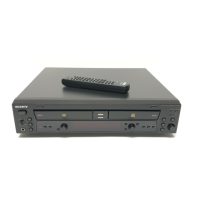
Information for identifying the unit based on its back panel.

SERVICING NOTE

NOTES ON HANDLING THE OPTICAL PICK-UP BLOCK OR BASE UNIT

Precautions for handling sensitive optical pickup components.

NOTES ON LASER DIODE EMISSION CHECK

Guidelines for safely checking laser diode emission.

LASER DIODE AND FOCUS SEARCH OPERATION CHECK

Procedure for checking laser diode and focus search operation.

TEST MODE

Test Mode Setup and Basic Functions

Instructions for entering, exiting, and using basic test modes.

Diagnostic and Functional Tests

Details on various diagnostic tests and functional checks available.

Playback Speed Adjustment

Procedure for adjusting playback speed in test mode.

ELECTRICAL ADJUSTMENTS

CD Section Adjustments (Deck A)

Adjustments for CD playback performance, including S-curve and RF level.

CD Base Unit Replacement Adjustment

Procedure for E-F Balance adjustment after replacing the CD Base Unit.

CD-R/RW SECTION

Test Setup and Equipment

Requirements for connecting and setting up test programs and equipment.

Repair Works Requiring Electrical Adjustment

Locating the Faulty Point

Laser Performance Checks

Procedures for checking laser power and assessing laser deterioration.

Self Diagnosis and Error Logging

Using self-diagnosis functions and acquiring error history data.

CDM65-RBD2 Electrical Adjustment

Laser and Playback Adjustments

Procedures for adjusting laser power and playback for CD/CD-R/CD-RW.

Specific Checks and Diagnostics

Performing VWDC checks and understanding NG messages.

Operation Check

Erasing the Error History

Procedure for clearing error history logs.

Playback Check using TCD-W032W

Method for checking playback using a specific test disc.

Supplementary Information

Method to Erase the CD-RW Disc

Instructions for erasing CD-RW discs for reuse.

DIAGRAMS

Diagram Types and References

Overview of diagram types including waveforms and board locations.

System Block Diagrams

High-level block diagrams of system sections.

Printed Wiring Boards (PWBs) and Schematics

Detailed PWB layouts and circuit schematic diagrams.

IC Details

IC block diagrams and pin function descriptions.

EXPLODED VIEWS

Main Unit Exploded Views

Exploded views of the main unit's exterior and chassis components.

Mechanism Exploded Views

Exploded views detailing the CD mechanisms and associated parts.

ELECTRICAL PARTS LIST

REVISION HISTORY

Related product manuals