EasyManua.ls Logo

Sony PDW-HD1500 Service Manual

Sony PDW-HD1500
160 pages
To Next Page IconTo Next Page
Page #1 background imageLoading...
Page #1 background image
PROFESSIONAL DISC RECORDER
PDW-HD1500
MAINTENANCE MANUAL
Volume 1 1st Edition (Revised 3)
MPEG TS BOARD
PDBK-201

Table of Contents

Other manuals for Sony PDW-HD1500

Question and Answer IconNeed help?

Do you have a question about the Sony PDW-HD1500 and is the answer not in the manual?

Sony PDW-HD1500 Specifications

General IconGeneral
BrandSony
ModelPDW-HD1500
CategoryCD Player
LanguageEnglish

Summary

Maintenance Manual Introduction

PDW-HD1500 Maintenance Manual Details

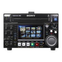
Manual for the Sony PDW-HD1500 Professional Disc Recorder, Volume 1, 1st Edition (Revised 3).

Safety Warnings and Precautions

Service Personnel and Electrical Safety Warnings

Emphasizes that only qualified personnel should perform servicing to prevent shock, fire, or injury.

Peripheral Device Connection Safety

Avoid connecting high-voltage peripheral device wiring to the network connector.

Battery Handling Safety Precautions

Battery Replacement and Disposal Warnings

Warns about explosion risk from incorrect battery replacement and instructs on proper disposal.

Laser Safety and Rack Installation Guidelines

Laser Radiation Hazard and Protection

Details laser diode properties and precautions against hazardous radiation exposure.

Rack Installation Safety and Environmental Considerations

Guidelines for rack installation including circuit loading, earth connection, and temperature control.

Service Overview and Circuit Functions

Cabinet Component Removal Procedures

Cabinet Disassembly and Manual Cartridge Ejection

Manual Cartridge Ejection Procedures

Instructions for manually ejecting a cartridge when the unit is powered off or the loader is inactive.

Circuit Protection and Fuse Replacement

Fuse Replacement Procedure and Safety

Provides instructions and safety precautions for replacing fuses.

Memory Component Replacement Procedures

Memory Backup Battery Replacement (HPR-23)

Detailed steps for replacing the memory backup battery on the HPR-23 board.

Firmware Update via Maintenance Menu

Firmware Update Using USB Memory

Step-by-step guide for updating the unit's firmware using a USB memory device.

Post-Repair Actions and Board-Specific Service

Optical Block Assembly Post-Repair Adjustments

Adjustments required after replacing the optical block assembly.

HPR-23 Board Post-Repair Re-settings

Re-settings and adjustments required after repairing or replacing the HPR-23 board.

Optical Block Assembly Handling Precautions

Electrostatic Discharge (ESD) Protection Measures

Procedures for grounding human body and work table to prevent ESD damage.

Physical Handling and Magnetic Interference Warnings

Guidelines for avoiding physical shock, touching components, and magnetic interference.

Error Messages Overview

Error Display and Logging Mechanisms

Explains where error codes are displayed and recorded, and the meaning of logger symbols.

Error Code Structure and Categories

Main and Sub Code Error Descriptions

Lists main error codes and their general descriptions for optical drive and loader issues.

Error Priority and Protection Mode Operation

Describes error priority display and the unit's protection mode during errors.

Optical Drive Control Error Codes (0X)

Loader and Optical Drive Sensor Errors

Data Read and Startup Operation Errors

CPU and Peripheral Interface Error Codes (91)

Synchronization and Device Interface Errors

Error 95: Device IC Interface Errors (Part 1)

Errors indicating communication issues between CPU and PCI bridge, i.LINK, MPEG devices, and video encoders.

Error 95: Device IC Interface Errors (Part 2)

Device IC Interface Errors (Memory, Optical Drive, Sensor)

Further errors related to device IC interfaces, including memory, optical drive, and sensor settings.

XDCAM Web Site Operations Overview

Web Interface Features and Menu Navigation

Describes the functionalities available through the XDCAM website, including status and maintenance menus.

Connecting to the XDCAM Web Site

Details the required tools and step-by-step procedure for accessing the unit's web interface.

XDCAM Web Site Status Menu Functions

Maintenance Menu Operations via Web Interface

Network Configuration Settings via Web Interface

Explains how to configure network-related settings like IP address, subnet mask, and DNS through the web interface.

Software Update via Web Browser (Internet Explorer)

Detailed steps for updating firmware using Internet Explorer and a firmware package file.

Maintenance Mode Functions Overview

MAINTENANCE MENU Structure and Navigation

Introduces the main menus within the maintenance mode: CHECK, ADJUST, SERVICE SUPPORT, OTHERS, SETUP, NETWORK, DRIVE.

Maintenance Mode Operation and Activation

Activating, Exiting, and Prohibiting Maintenance Mode

Procedures for entering and exiting the maintenance mode, including the use of the S2701 switch.

Comprehensive Maintenance Menu Guide

Maintenance Mode: System Checks

Maintenance Mode: System Adjustments

Video Output Level and Frequency Adjustments

Guides for adjusting composite video output levels and free-run frequencies for HD and SD signals.

Audio System, Battery, and NV-RAM Adjustments

Procedures for audio system adjustment, battery voltage adjustment, and NV-RAM control.

Service Support and Diagnostics Functions

Error Log Management and Display

How to view registered error logs and manage them using DIAG CONTROL.

Optical Drive Component Diagnostic Checks

Optical Drive Sensor Diagnostic Procedures

Loader Operation and System Checks

Optical Block and Limit Sensor Diagnostics

Optical Drive Limit and Spindle Motor Diagnostics

Optical Drive Actuator Diagnostic Procedures

Optical Drive Laser and ND Filter Diagnostics

Optical Drive Skew and Servo Adjustments

Servo and Skew Adjustment Procedures

Guides for adjusting Servo_1, Servo_2, and performing skew adjustments.

Optical Drive Adjustment Procedures

Periodic Maintenance and Component Overview

Main Parts Replacement Procedures Overview

Power Supply Unit Replacement Procedure

Loader Assembly Replacement Procedure

Cleaner Assembly Replacement Procedure

Loading Motor Assembly Replacement Procedure

Drive Sub Assembly Removal and Reinstallation

Optical Block Assembly Replacement Procedure

Optical Block Assembly Removal Steps

Comprehensive steps for removing the optical block assembly, including panel and loader removal.

Gear Assemblies Replacement Procedures

Seek Motor Assembly Replacement Procedure

Spindle Motor Replacement Procedure

Fan Motor Replacement Procedures

Circuit Board Removal and Reinstallation

Optical Drive Alignment Procedures

Optical Drive Alignment Precautions and Fixtures

Safety, tools, and fixture requirements for optical drive alignment.

Preparations for Optical Drive Adjustment

Steps to prepare the unit before starting optical drive alignment procedures.

Servo and Skew Adjustment Procedures

Servo1 Automatic Adjustment Steps

Detailed procedure for performing automatic Servo1 adjustment using an alignment disc.

Tangential Skew Adjustment Procedure

Steps for performing tangential skew adjustment on the optical drive.

Radial Skew Adjustment Procedure

Steps for performing radial skew adjustment, including using locking compound.

Drive Calibration and Data Management

Servo2 Automatic Adjustment Procedure

Steps for performing automatic Servo2 adjustment, including loader installation and media log clearing.

Electrical Alignment Procedures Overview

Electrical Alignment Precautions and Tools

Safety guidelines, required tools, and fixtures for electrical alignment.

Accessing Adjustment Items in Maintenance Mode

Steps to display specific electrical alignment items within the maintenance menu.

HD Free-Running Frequency Adjustment

HD 74 MHz VCO Adjustment Procedure

Detailed procedure for adjusting the HD 74 MHz VCO, including oscilloscope and frequency counter settings.

SD Free-Running Frequency Adjustment

SD 27 MHz VCO Adjustment Procedure

Procedure for adjusting the SD 27 MHz VCO, including oscilloscope and frequency counter settings.

Video System Alignment Procedures

VPR-99 Board Video System Alignment Overview

General guide for video system alignment on the VPR-99 board, specifying 59.94 Hz and 50 Hz modes.

Preparation for 59.94 Hz Video Alignment

Steps to prepare the unit and settings for 59.94 Hz video system alignment.

Composite Video Output Adjustment (59.94 Hz Mode)

Procedure for adjusting composite video output levels using a waveform monitor.

Preparation for 50 Hz Video Alignment

Steps to prepare for 50 Hz mode video alignment, including resetting settings.

Composite Video Output Adjustment (50 Hz Mode)

Procedure for adjusting composite video output levels in 50 Hz mode using a waveform monitor.

Perfection of 50 Hz Mode Alignment

Final steps to complete the 50 Hz mode video alignment and save data.

SDI Output System Adjustment

SDI Output Adjustment Overview

General information on adjusting VCO free-running frequencies for SDI output encoders.

VCO Free-running Frequency Automatic Adjustment

Procedure for automatic adjustment of VCO free-running frequencies for SDI output, including failure diagnosis.

Audio System Adjustment Procedures

Audio System Adjustment Overview and Tools

Lists tools, fixtures, and preparation steps for audio system adjustment.

Analog Audio Output System Adjustment (Channel 1 & 2)

Steps for adjusting analog audio output levels for both channels.

Audio Input Adjustment and Power Voltage Calibration

Analog Audio Input System Adjustment (Channel 1 & 2)

Procedure for adjusting analog audio input levels for both channels.

DC-IN +12V Voltage Adjustment Procedure

Steps for adjusting the DC-IN +12V input voltage and handling adjustment failures.

Final Safety Checks and Leakage Testing

AC Leakage Test Procedure and Limits

Outlines safety checks for AC leakage from exposed metal parts, including measurement methods.

Related product manuals