EasyManua.ls Logo

Sony PHC-Z10 User Manual

Sony PHC-Z10
58 pages
To Next Page IconTo Next Page
Page #1 background imageLoading...
Page #1 background image
PHC-Z10
US Model
Canadian Model
E Model
SERVICE MANUAL
PERSONAL COMPONENT SYSTEM
— Continued on next page —
SPECIFICATIONS
Model Name Using Similar Mechanism NEW
CD
CD Mechanism Type KSM-213CCM
Section
Optical Pick-up Name KSS-213C
TC
Model Name Using Similar Mechanism NEW
Section
Tape Transport Mechanism Type MF-PHCZ10
AUDIO POWER SPECIFICATIONS
POWER OUTPUT AND TOTAL
HARMONIC DISTORTION
With 6 loads, both channel driven from 120
- 10 000 Hz; rated 50 W per channel-minimum
RMS power, with no more than
10 % total harmonic distortion from 250
milliwatts to rated output.
Other Specifications
CD player section
System
Compact disc digital audio system
Laser diode properties
Material: GaAlAs
Wave length: 780 nm
Emission duration: Continuous
Laser output: Less than 44.6 µW
(This output is the value measured at a distance of
about 200 mm from the objective lens surface on
the optical pick-up block with 7 mm aperture.)
Spindle speed
200 r/min (rpm) to 500 r/min (rpm) (CLV)
Number of channels
2
Frequency response
20 - 20 000 Hz +1/–2 dB
Radio section
Frequency range
FM: 87.6 - 108 MHz
AM: 530 - 1 710 kHz
Antenna
FM: Lead antenna
AM: Loop antenna
Cassette-corder section
Recording system
4-track 2 channel stereo
Fast winding time
Approx. 100 s (sec.) with Sony cassette C-60
Frequency response
TYPE I (normal): 100 - 10 000 Hz
Ver 1.0 2000. 05
Question and Answer IconNeed help?

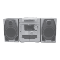
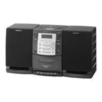
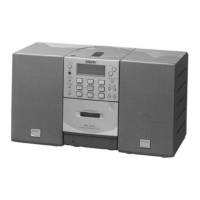
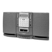
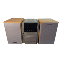
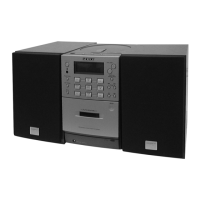
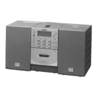
Do you have a question about the Sony PHC-Z10 and is the answer not in the manual?

Sony PHC-Z10 Specifications

General IconGeneral
BrandSony
ModelPHC-Z10
CategorySpeaker System
Speaker TypePortable Speaker
Charging Time4 hours
WaterproofIPX5

Summary

Specifications

Audio Power Specs

Detailed power output and harmonic distortion.

Safety Precautions and Warnings

Handling Sensitive Components

Notes on repairing circuit boards, chip components, and optical pick-ups.

Laser Safety and Component Warnings

Laser emission check safety and critical component identification.

Safety Check-out Procedures

AC Leakage Testing

Method for measuring AC leakage current from exposed metal parts.

Section 2 Disassembly

Component Disassembly Steps

Detailed instructions for dismantling side panels, mechanisms, and boards.

Section 3 Mechanical Adjustments

Tape Mechanism Adjustments

Procedures for tape torque, tension, speed, and azimuth adjustments.

Section 4 Electrical Adjustments

Tuner Section Adjustments

FM/AM frequency coverage and tracking calibration procedures.

Section 5 Diagrams

Section 6 Exploded Views

Related product manuals