Do you have a question about the Sony PMC-D305 and is the answer not in the manual?
Details technical specifications for audio, CD, and radio sections.
Procedures for safety checks and AC leakage testing after service.
Precautions for handling optical components and laser diode checks.
Warning about critical safety-related components.
General user operations for playing CD, radio, and tape.
Step-by-step guide to playing compact discs.
Instructions for tuning into radio stations.
Guide for playing cassette tapes.
Steps for recording audio onto cassette tapes.
Overview of the set disassembly sequence by section.
Instructions for removing the rear cabinet.
Steps for removing the lower case section.
Procedure for disassembling the CD cabinet.
Procedure for disassembling the optical pick-up assembly.
Precautions and methods for torque and tape tension measurement.
Adjustments specific to the tape deck, including output level and azimuth.
Procedures for adjusting AM/FM/LW frequency coverage and tracking.
Procedures for E-F Balance and Focus Bias adjustments.
Schematic diagrams for the tuner section.
Schematic diagrams for the CD section.
Schematic diagrams for the main circuitry.
Schematic diagrams for the control section.
Schematic diagrams for the power supply and amplifier sections.
Exploded views of the player's case and front cabinet.
Exploded views of the CD cabinet and optical pick-up.
Exploded views of the tape mechanism and speakers.
List of electrical components for the audio section.
List of electrical components for the tuner section.
Lists of hardware, packing materials, and accessories.
Details changes in parts due to production updates.
Corrected procedure for entering and releasing test mode.
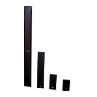
| Type | Speaker System |
|---|---|
| Brand | Sony |
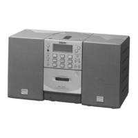
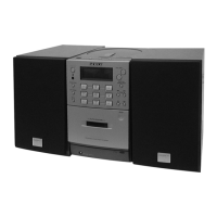
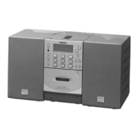
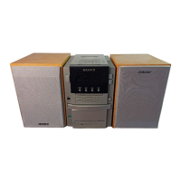
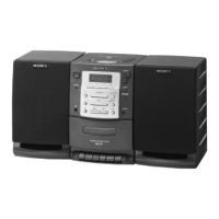
| Model | PMC-D305 |
| Frequency Response | 50 Hz - 20 kHz |
| Impedance | 8 Ohms |