– 74 –
1 AC CHK I AC check input
2 C-SCOR I CD-SCOR input
3 RMC I Remote commander input
4 C-XRST O CD system reset output
5 C-XLAT O CD DSP (IC702) command
6 C-DAT O CD DSP (IC702) command data output
7 C-CLK O Clock output for CD DSP (IC702) command
8 C-DOOR I Open/close detection input “L”: close “H”: open
9 328/332 I 328/332 select input (Fixed at “H”)
10 C-SENC I CD-SENS input
11 C-SQCK O Clock output for CD SUBQ
12 C-SQSO I CD SUBQ input
13 T-BIAS I Tape REC BIAS input
14 – – Not used (Open)
15 T-REC I Tape REC input
16 T-SOL O Plunger control output
17 T-MODE O HEAD switching output
18 T-AMS I AMS sensitivitiy switching
19 T-MCON O Motor control output “H”: Motor on
20 P-CON O Power on/off control output
21 V-CLK O Volume clock output
22 V-DAT O Volume data output
23 V-CE O Electrical volume (IC302) chip enable output
24 R-ST I Stereo detection input
25 R-COUNT I Tuner PLL IC count input
26 R-DAT O Tuner PLL IC data output
27 R-CLK O Tuner PLL IC clock output
28 R-CE O Tuner PLL IC chip enable output
29 9K/10K I 9K/10K select input (Not used)
30 T-STAT I Tape detection input
31-34 KEY-0-3 I Key return signal input
35 INIT O Initial setting output
36 SIMUKE I Destination setting terminal
37 SFC O Shift clock on/off out
38 RST I Reset input
39 EXTAL1 I Clock oscillation input (4.19MHz)
40 XTAL1 O Clock oscillation output (4.19MHz)
41 VSS – Ground (for A/D converter)
42 XTAL2 O Clock oscillation output (Open)
43 EXTAL2 I Clock oscillation output (Fixed at “L”)
44 AVREF I Reference voltage input (for A/D converter)
45 AVSS – Ground (for A/D converter)
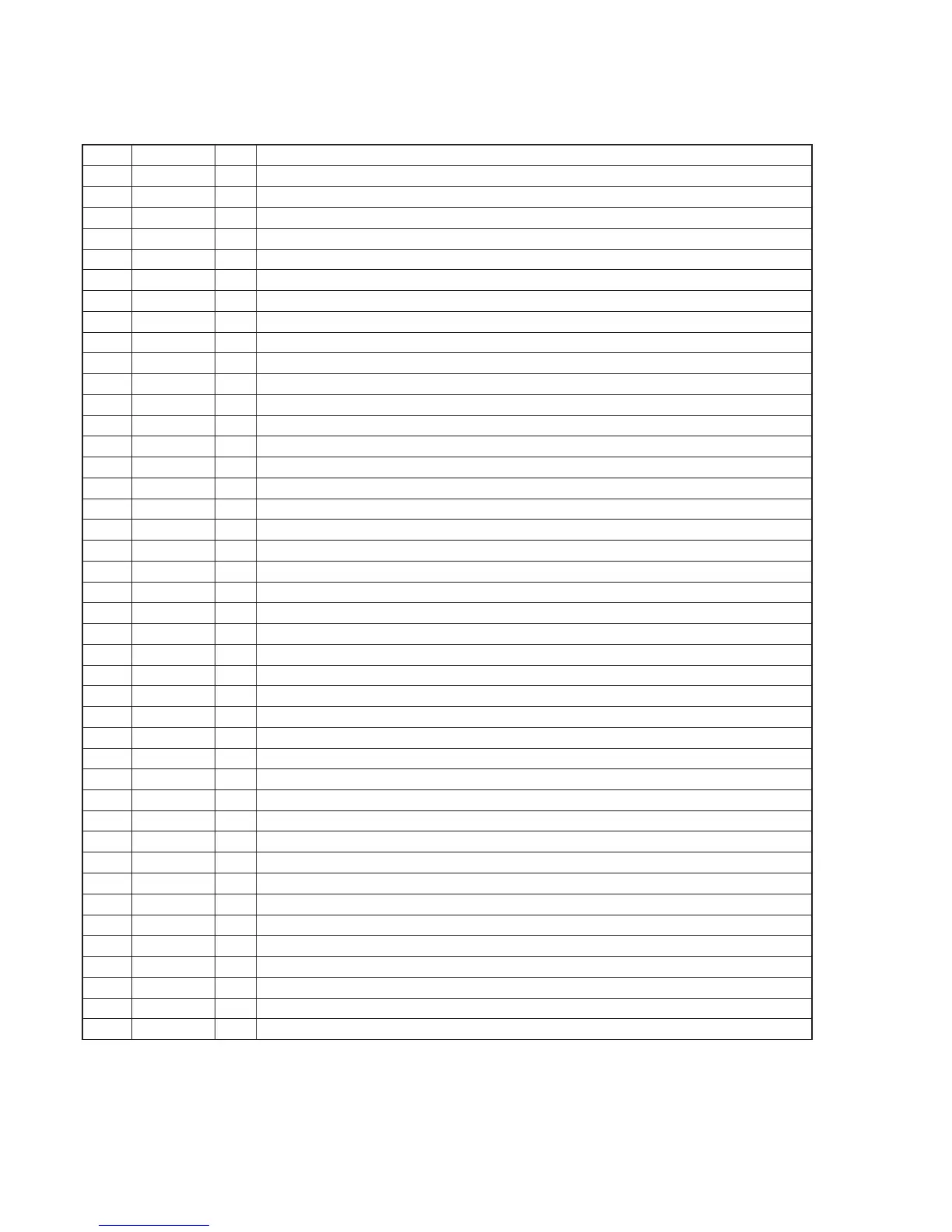
Pin No. Pin Name I/O Function
6-13. IC PIN FUNCTION DESCRIPTION
CONTROL BOARD IC801 CXP83120A-019Q (SYSTEM CONTROL, LCD DRIVE)