– 75 –
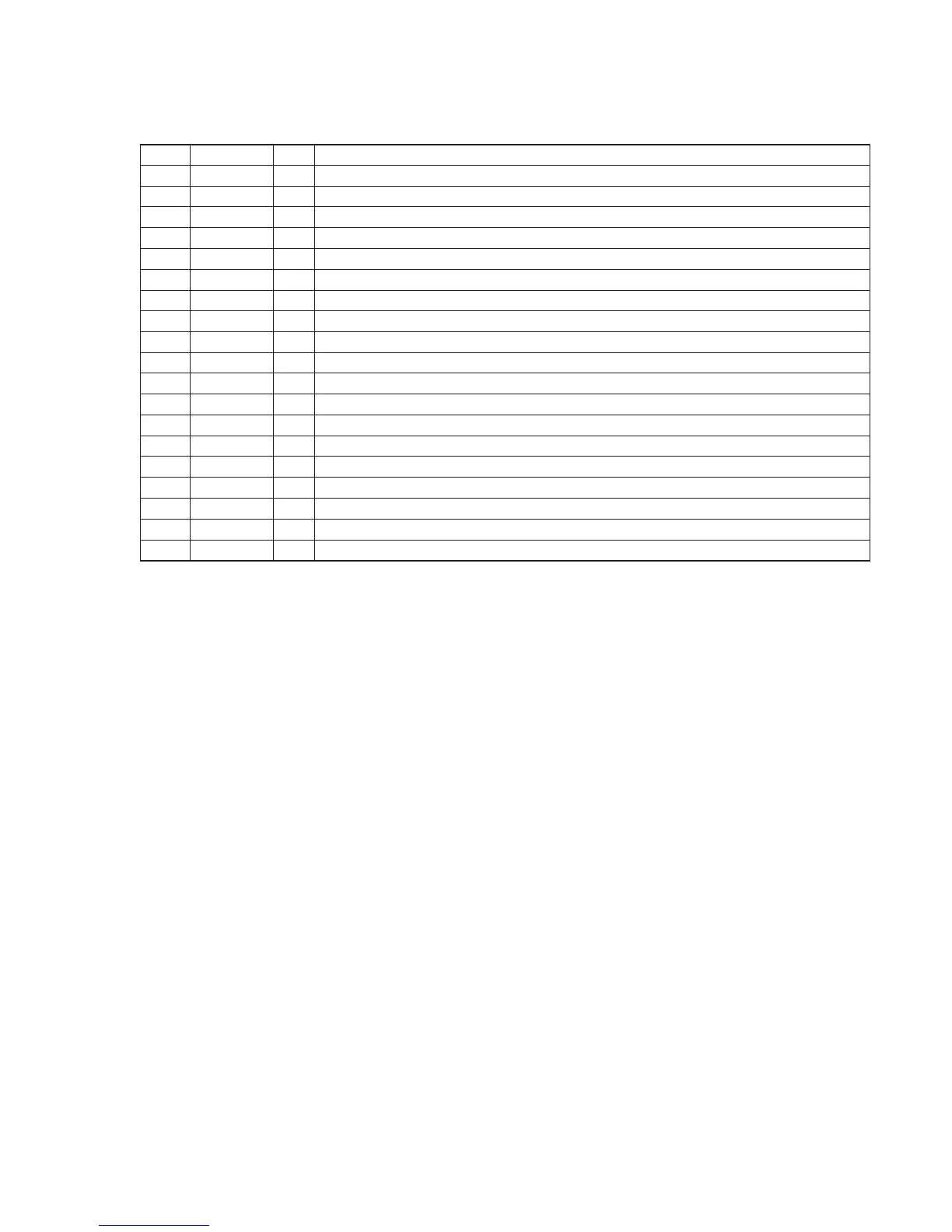
46 VL O LCD bias resistor current control terminal (Cut off at standby)
47-49 VLC3-1 – LCD bias power supply terminal
50-53 COM0-3 O LCD common signal output terminal
54-77 SEG0-23 O LCD segment signal output terminal
78-84 NC – Not used (Open)
85-87 – – Not used (Open)
88 BL-CONT O LCD Back light control output
89 VDD – Power supply (+5V)
90 NC – Connected to the power supply
91 VSS – Ground
92 TX O Crystal connection for clock oscillation (32.768kHz)
93 TEX I Crystal connection for clock oscillation (32.768kHz)
94 C-MUTE O Mute output for CD
95 B-MUTE O Mute output for Tuner
96 A-MUTE O Mute output for Audio
97 ISS1 I ISS1 switch input
98 ISS2 I ISS2 switch input
99 T-END I Tape end detection input
100 NC – Not used (Open)
Pin No. Pin Name I/O Function


 To Next Page