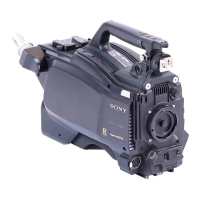
Do you have a question about the Sony Power HAD FX HSC300R and is the answer not in the manual?
Explains the manual's scope and target audience for service engineers.
Lists other manuals provided with the unit for comprehensive support.
Lists registered and unregistered trademarks used in the document.
Details the unit's various connectors, their types, and signal assignments.
Provides diagrams showing the physical placement of internal PCBs within the unit.
Explains the functionality of key circuit blocks and their interconnections.
Outlines important considerations and procedures for replacing internal components.
Describes recommended maintenance tasks and inspection schedules for longevity.
Provides a step-by-step guide for replacing the unit's internal lithium battery.
Details procedures for cleaning optical and electrical connectors to ensure signal integrity.
Lists necessary fixtures and calibrated measuring equipment for adjustments.
Explains how to update the camera application and operating system via USB.
Details Programmable Logic Devices (PLDs) and procedures for upgrading their data.
Describes an alternative method for updating software or PLD data when standard methods fail.
Guides on configuring intercom settings for different headset types and operations.
Covers procedures for connecting, disconnecting, and forming flexible card wires and coaxial cables.
Explains the ID numbering system for CCD blocks, indicating type and serial number.
Lists circuit protection components like fuses and thermistors, including their specifications.
Provides guidelines for using lead-free solder during board repairs.
Details the procedure for removing and reinstalling the camera's inside panel assembly.
Explains how to access and remove the TRIAX version's outside panel assembly.
Details the process for removing the fiber optic version's outside panel assembly.
Covers the replacement procedures for the CCD unit and related boards.
Describes the steps to remove and replace the CD-78 board.
Details the procedure for replacing the SDI-117 board.
Outlines the steps for removing and replacing the DPR-358 board.
Provides instructions for replacing the internal DC cooling fan.
Covers the replacement procedures for the SY-430 and AT-189 circuit boards.
Details the process for removing and replacing the main power supply unit.
Explains how to replace the MB-1207 motherboard.
Describes the steps to remove and reinstall the main connector panel assembly.
Provides instructions for replacing the unit's intercom panel assembly.
Covers the replacement of the CN-3647 and SW-1608A circuit boards.
Lists required equipment, precautions, and data files for electrical adjustments.
Details the procedure for performing automatic adjustments using the MSU-1000 control panel.
Provides detailed procedures for various electrical alignment adjustments.
Covers adjustments for video signal levels like H/V ratio and detail.
Adjusts for variations when using Neutral Density (ND) filters.
Details procedures for compensating residual point noise (RPN) in the image sensor.
Lists required equipment and precautions for digital triax system alignment.
Details the frequency adjustment procedure for the 1.4-MHz modulation circuit.
Covers tuning adjustments for the demodulation circuit.
Describes the different types of files used for managing camera settings and data.
Explains how to store and read operator files for camera settings.
Details the operation of preset operator files for factory settings.
Covers storing, calling, and copying scene files for specific shooting conditions.
Explains how to store and manage reference files for custom paint data.
Details the creation and management of lens files for compensating optical characteristics.
Describes the process of adjusting and storing OHB file data for CCD block maintenance.
Lists the setting items that can be stored in various file types.
Introduces the structure and operation of the camera's setup menu.
Details the SERVICE menu options for maintenance and adjustment procedures.
Provides important notes regarding safety components, part standardization, and stock availability.
Presents detailed exploded diagrams of the camera's internal and external assemblies.
Lists the accessories included with the camera unit.
Presents various block diagrams illustrating the camera's internal signal flow and component relationships.
Illustrates the overall wiring scheme and connections between major assemblies.