44
SDI Connector Input/Output Specifications
Appendix
In: SDI signal input. In1 and In2 represent inputs 1 and 2,
respectively, of the dual-system input of each port.
Input 1 is the main port, and input 2 is the sub-port.
For single system signal formats transferred using
more than one SDI cable, it is represented by In1-1,
In1-2, and so on.
IM (Input Monitor): Input SDI signal output for monitor.
IM1 and IM2 represent inputs 1 and 2, respectively,
when using dual-system input.
DC: Down-converted 4K to HD signal output for monitor.
Char: Superimposed character information output for
monitor. For dual-system input, Char1 and Char2
represent monitor outputs 1 and 2, respectively.
–: Not used.
a) The format of the signals output from the SDI IN/OUT 9 and 10
connectors is set when the video format is specified on the [Board] tab of
the [System] screen of the web menu. The supported formats for the SDI
IN/OUT 9 and 10 connectors vary depending on the signal format
specified for the SDI IN/OUT 1 to 8 connectors.
b) Two input ports are used to input a single system signal.
c) 1280:720p is connected using 1.5G SDI.
d) To simultaneously record a normal-speed HD signal, connect a normal-
speed HD signal to the SDI IN/OUT 9 connector.
• To connect a BPU4000/BPU4800 for HD 4x speed
recording, connect the SDI-1 to SDI-4 connectors of the
BPU4000/BPU4800 to the SDI-1 to SDI-4 connectors of
the unit.
• To connect a BPU4000/BPU4800 for HD 6x or 8x speed
recording, connect the SDI-1 to SDI-4 connectors of the
BPU4000/BPU4800 to the SDI-1 to SDI-4 connectors of
port A of the unit, and connect the SDI-5 to SDI-8
connectors of the BPU4000/BPU4800 to the SDI-1 to
SDI-4 connectors of port B of the unit.
For output ports
Out: Represents all SDI IN/OUT 1 to 8 connector outputs.
For single system signal formats transferred using
more than one SDI cable, it is represented by Out1-1,
Out1-2, and so on. 8-system output is supported for
formats that are transferred using one SDI cable
(Single Link), 4-system output for formats using two
cables (Dual Link), and 2-system output for formats
using four cables (Quad Link).
DC: Down-converted 4K to HD signal output for monitor.
Char: Superimposed character information output for
monitor.
–: Not used.
a) When [Output Port SDI-1,2,3,4] is set to [Off] on the [Setup] tab of the
[System] screen in the web menu, no signal is output.
b) The format of the signals output from the SDI IN/OUT 9 and 10
connectors is set when the video format is specified on the [Board] tab of
the [System] screen of the web menu. The supported formats for the SDI
IN/OUT 9 and 10 connectors vary depending on the signal format
specified for the SDI IN/OUT 1 to 8 connectors.
c) 1280:720p is connected using 1.5G SDI.
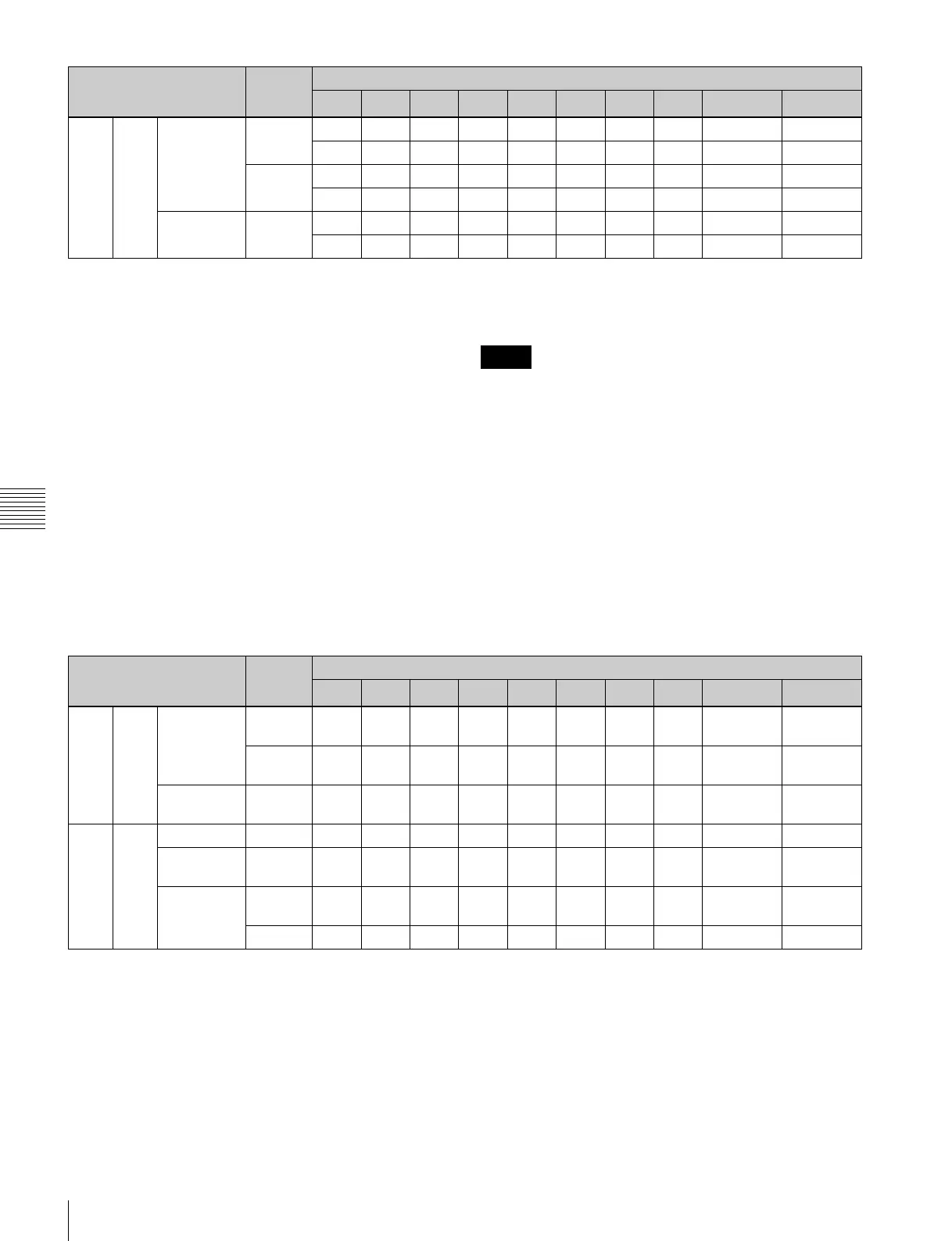
HD 422 400i/479i
b)
1.5G In1-1 In1-2 In1-3 In1-4 IM1-1 IM1-2 IM1-3 IM1-4 In2/Char
d)
Char
In1-5 In1-6 In1-7 In1-8 IM1-5 IM1-6 IM1-7 IM1-8 – –
3G In1-1 In1-2 – – IM1-1 IM1-2 – – In2/Char
d)
Char
In1-3 In1-4 – – IM1-3 IM1-4 – – – –
400p/
479p
b)
3G/
1.5G
c)
In1-1 In1-2 In1-3 In1-4 IM1-1 IM1-2 IM1-3 IM1-4 In2/Char
c)
Char
In1-5 In1-6 In1-7 In1-8 IM1-5 IM1-6 IM1-7 IM1-8 – –
Format SDI SDI IN/OUT connector
1 2 3 4 5 6 7 8
9
a)
10
a)
Notes
Format SDI SDI IN/OUT connector
1
a)
2
a)
3
a)
4
a)
5 6 7 8
9
b)
10
b)
4K 422 23p/Psf to
29p/Psf
1.5G Out1-
1
Out1-
2
Out1-
3
Out1-
4
Out1-
1
Out1-
2
Out1-
3
Out1-
4
DC/Char DC/Char
3G Out1-
1
Out1-
2
Out1-
1
Out1-
2
Out1-
1
Out1-
2
Out1-
1
Out1-
2
DC/Char DC/Char
50p/59p 3G Out1-
1
Out1-
2
Out1-
3
Out1-
4
Out1-
1
Out1-
2
Out1-
3
Out1-
4
DC/Char DC/Char
HD 422 50i/59i 1.5G Out Out Out Out Out Out Out Out Char Char
23p/Psf to
29p/Psf
1.5G Out Out Out Out Out Out Out Out Char Char
50p/59p 1.5G Out1-
1
Out1-
2
Out1-
1
Out1-
2
Out1-
1
Out1-
2
Out1-
1
Out1-
2
Char Char
3G/1.5G Out Out Out Out Out Out Out Out Char Char
 Loading...