Do you have a question about the Sony PXW-X160 and is the answer not in the manual?
Use parts with the same characteristics as the original ones, especially for safety-critical components.
Check that screws, parts, and wiring are reassembled correctly and that the service area is not deteriorated.
Explains the self-diagnosis function that starts when an error occurs and displays a code on the LCD.
A table listing self-diagnosis codes, symptoms/states, and corresponding corrections for troubleshooting.
General notes on operating procedures and precautions to follow during service.
Precautions for handling flexible boards, ensuring proper connection and avoiding damage.
Steps to write adjustment values after replacing the EVF display device, including recording and inputting data.
Steps to write adjustment values when replacing the VC board, involving reading and saving data before replacement.
Steps to write adjustment values when VC board replacement occurs and values cannot be read, using QR code.
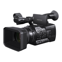
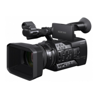
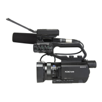
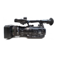
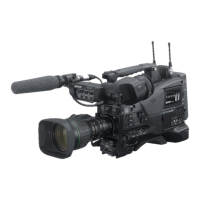
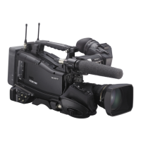
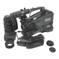
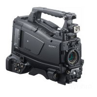
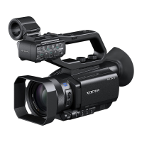
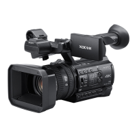
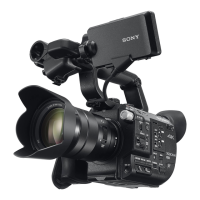
Diagrams and lists to identify the various parts of the camcorder by section.
Electrical parts list for the DD-1011 board, detailing various components like capacitors, diodes, and resistors.
Electrical parts list for the VC-1030 board, detailing numerous components.
| Sensor type | CMOS |
|---|---|
| Total megapixels | - MP |
| Optical sensor size | 1/3 \ |
| Filter size | 82 mm |
| Digital zoom | - x |
| Optical zoom | 25 x |
| Image stabilizer | Yes |
| Focal length range | 3.7 - 92.5 mm |
| Interchangeable lens | - |
| Maximum aperture number | 11 |
| Minimum aperture number | 1.6 |
| Maximum focal length (35mm film equiv) | 650 mm |
| Minimum focal length (35mm film equiv) | 26 mm |
| Camcorder media type | Memory card |
| Disc types supported | No |
| Compatible memory cards | SD, SDHC |
| Internal storage capacity | - GB |
| Camera shutter speed | 1/32 - 1/2000 s |
| Display diagonal | 3.5 \ |
| Display aspect ratio | 16:9 |
| Viewfinder type | Electronic |
| Viewfinder resolution | 2360000 pixels |
| Viewfinder screen size | 0.5 \ |
| Camcorder type | Shoulder camcorder |
| Product color | Black |
| Video resolutions | 720 x 576, 1280 x 720, 1920 x 1080 pixels |
| Video formats supported | AVCHD, DV, MPEG, MPEG2 |
| Maximum video resolution | 1920 x 1080 pixels |
| Audio formats supported | LPCM |
| Headphone outputs | 1 |
| Headphone connectivity | 3.5 mm |
| USB 2.0 ports quantity | USB 2.0 ports have a data transmission speed of 480 Mbps, and are backwards compatible with USB 1.1 ports. You can connect all kinds of peripheral devices to them. |
| Battery type | BP-U30 |
| Battery capacity | - mAh |
| Battery life (max) | - h |
| Battery recharge time | 2.23 h |
| Storage temperature (T-T) | -20 - 60 °C |
| Operating temperature (T-T) | 0 - 40 °C |
| Cables included | AC, USB |
| Depth | 412 mm |
|---|---|
| Width | 191.5 mm |
| Height | 201.5 mm |
| Weight | 2700 g |