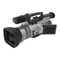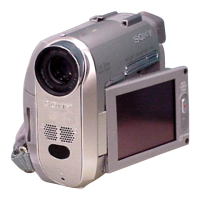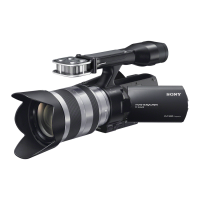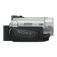
Do you have a question about the Sony RMT-502 and is the answer not in the manual?
| Device Type | Remote Control |
|---|---|
| Connectivity | Infrared |
| Compatible With | Sony Camcorders |
| Function | Remote operation of camcorder |
| Battery | CR2025 |
Detailed technical specifications of the CCD-F555E video camera.
Details on video recording system, audio recording, video signal, and audio output.
Information on video and audio input/output connectors and their specifications.
Details on power requirements, including battery and AC adapter specifications.
List of accessories included with the camera package.
Pre-service checks to ensure the camera is safe and functional before repair.
List of semiconductors for correction and their associated part numbers.
Diagrams showing the location of semiconductors on the circuit boards.
Procedure for cleaning the video heads and checking for dirt.
Diagrams and labels identifying the external and internal parts of the camera.
Instructions on how to connect and use different power sources.
Guidance on connecting and using the battery pack.
Instructions for setting the defense time using the remote controller.
Procedure for inserting a video cassette into the camera.
Steps for recording a picture using automatic adjustment features.
Instructions for superimposing text titles onto video recordings.
Procedure for recording and displaying the age of a child.
Guidance on connecting the camera for playback.
Step-by-step guide to remove the cassette lid assembly.
Procedure for disassembling the upper cabinet.
Procedure for disassembling the lower cabinet.
Instructions for removing the head cover.
Procedure to remove the microphone board.
Guide to removing the electronic viewfinder assembly.
Steps for removing the camera block assembly.
Procedure for removing the CCD imager from the CD-60 board.
Instructions for removing the VA-70 board.
Diagrams showing the internal views of the camera mechanism.
Diagram showing the location of various circuit boards within the camera.
A comprehensive block diagram illustrating the camera's system architecture.
Detailed block diagram of the camera section, focusing on the CD-60 board.
Block diagram illustrating the DT-77 board functionality.
Partial block diagram for the VC-96 board, detailing camera process.
Description of the VC-96 board's function and pin assignments.
Details on the IC501 microcomputer and its role in system control.
Block diagram detailing the camera section, focusing on specific ICs.
Schematic diagram illustrating the overall frame connections.
Collection of diagrams for various printed wiring boards.
Component side layout for the CD-60 board.
Schematic diagram for the CD-60 board.
Schematic diagram for the DT-77 board.
Schematic diagram for the VC-96 board, camera process section.
Component layout for the VC-96 board.
Conductor layout for the VC-96 board.
Schematic diagram for the second part of the VC-96 board.
Component layout for the VF-26 board (View Finder).
Component layout for the VF-27 board (View Finder).
List of electrical components for CC-61 and CD-60 boards.
Detailed parts list for the CD-60P board.
List of electrical components for the CT-40 board.
List of components for the CT-40 board, including resistors and capacitors.
Parts list for the CT-40P board.
Component lists for FP-249, FP-250, and FP-252 boards.
Component lists for FU-104P, LI-36P, and MC-82P boards.
Parts list for MC-82P and SS-136 boards.
Detailed list of capacitors for the SS-136 board.
List of transistors and resistors for the SS-136 board.
Detailed list of resistors for the SS-136 board.
Component lists for SW-175P, VA-70P, and VA-70PB boards.
Capacitor list for VA-70P and VA-70PB boards.
Resistor list for VA-70P and VA-70PB boards.
Component lists for VA-70P, VA-70PB, and VC-96P boards.
Detailed list of resistors for the VC-96P board.
Capacitor and connector list for the VC-96P board.
Resistor list for the VC-96P board.
Component lists for VF-26P and VF-27P boards.
Resistor list for VF-26P and VF-27P boards.
Capacitor and connector list for VF-26P and VF-27P boards.
Procedure for setting the track shift mode.
Steps required before performing adjustments.
Instructions for transferring service mode using the RM-95 remote.
Map detailing the memory allocation for Senser LANC.
Guide to camera system adjustment procedures.
Procedure for adjusting the flange back.
Method for performing auto focus adjustment.
Procedure to check the camera DC-DC converter.
Initial settings for the EVR.
Adjustment for flange back on the CD-60 board.
Procedure for Vsus adjustment on the VC-96 board.
Steps for iris adjustment on the VC-96 board.
Procedure for Hall adjustment on the VC-96 board.
Steps for adjusting AGC on the VC-96 board.
Procedure for adjusting matrix gain.
Steps for adjusting Ys gain.
Procedure for Yh level adjustment.
Procedure for C1 gain adjustment.
Steps for adjusting sync level.
Procedure for setup adjustment.
Steps for white clip adjustment.
Procedure for burst level adjustment.
Method for color reproduction adjustment using a vectorscope.
Method for color reproduction adjustment using an oscilloscope.
Procedure for AE offset adjustment.
Steps for auto white balance adjustment.
Procedure for shutter in/out adjustment.
Checking procedure for indoor white balance.
Procedure for checking auto white balance.
Adjustment procedures for the digital titler system.
Method for adjusting chroma phase.
Adjustment procedures for the electronic viewfinder system.
Procedure for centering the viewfinder image.
Procedure for adjusting focus.
Steps for adjusting aberrations.
Procedure for adjusting horizontal oscillation frequency.
Steps for adjusting horizontal amplitude.
Adjustment procedures for Type B viewfinder system.
Procedure for adjusting brightness and contrast.
Procedure for focus adjustment on the VF-26 board.
Diagrams showing the arrangement of parts used for adjustments.
Steps to prepare for video block adjustments.
Instructions on connecting test equipment for adjustments.
Procedure to set the REC mode without a dedicated REC switch.
Important notes regarding video block adjustments.
List and description of alignment tapes used for camera adjustments.
Specifications for input/output levels and impedance.
Explanation of the service mode operation.
Procedure for adjusting and storing adjustment data.
Procedure for checking the REC switch.
Procedure for checking the mode switches.
Procedure for checking various switches.
Procedure for adjusting power supply voltages.
Procedure for adjusting oscillation frequency.
Procedure for checking power supply voltages.
Procedures for system control adjustments.
Procedure for servo system adjustment.
Procedure for adjusting playback frequency characteristics.
Procedure for CH1 adjustment.
Procedure for checking crystal oscillator frequency.
Procedure for adjusting REC EE level.
Procedure for IR adjustment.
Procedure for chroma comb filter adjustment.
Procedure for emphasis Y level adjustment.
Procedure for PB Y level adjustment.
Procedure for PB CCD input level adjustment.
Procedure for Y FM deviation adjustment.
Procedure for Y FM carrier frequency adjustment.
Procedure for chroma emphasis adjustment.
Procedure for REC C RF level adjustment.
Procedure for REC Y level adjustment.
Procedure for quasi burst phase adjustment.
Procedure for delay burst phase adjustment.
Method for adjusting quasi burst phase using a monitor.
Procedures for character generator adjustments.
Procedure for SG frequency adjustment.
Procedure for adjusting character position.
Procedures for adjusting the audio system.
Procedure for IR adjustment.
Procedure for checking 1.5 MHz frequency.
Procedure for checking 1.7 MHz carrier frequency.
Procedure for 1.5 MHz recording level adjustment.
Procedure for 1.7 MHz recording level adjustment.
Procedure for REC Matrix L-R adjustment.
Procedure for 1.5 MHz deviation adjustment.
Procedure for PB Matrix L adjustment.
Procedure for PB Matrix R adjustment.
Checking overall level and separation characteristics.
Procedure for checking overall distortion.


