EasyManua.ls Logo

Sony RMT-809 User Manual

Sony RMT-809
176 pages
To Next Page IconTo Next Page
Page #1 background imageLoading...
Page #1 background image
DCR-TRV9/TRV9E
RMT-808/809
US Model
Canadian Model
DCR-TRV9
AEP Model
UK Model
Australian Model
Chinese Model
DCR-TRV9E
E Model
Hong Kong Model
Tourist Model
DCR-TRV9/TRV9E
SERVICE MANUAL
DIGITAL VIDEO CAMERA RECORDER
MICROFILM
C MECHANISM
Photo: DCR-TRV9E
RMT-809
For MECHANISM ADJUSTMENTS, refer to the “DV
MECHANICAL ADJUSTMENT MANUAL
C MECHANISM ”
(9-974-050-11)
NTSC model: DCR-TRV9
PAL model: DCR-TRV9E
SPECIFICATIONS
— Continued on next page —
Ver 1.0 1998.04

Table of Contents

Question and Answer IconNeed help?

Do you have a question about the Sony RMT-809 and is the answer not in the manual?

Sony RMT-809 Specifications

General IconGeneral
BrandSony
ModelRMT-809
CategoryCamcorder
LanguageEnglish

Summary

SERVICE MANUAL

SPECIFICATIONS

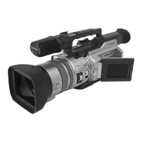
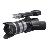
Detailed technical features and operational parameters of the camcorder.

SAFETY INFORMATION

Safety-Related Component Warnings

Critical components identified for safe operation and replacement.

Safety Check-Out Procedures

Essential checks to perform after repair before releasing the unit.

SERVICE NOTES

Power Supply During Repairs

Methods to prevent power shut-off during repair procedures.

Cassette Removal Without Power

Procedure for forcibly ejecting a cassette when power is off.

SELF-DIAGNOSIS FUNCTION

Self-Diagnosis Display and Service Mode

Viewfinder display for error codes and service mode access.

Self-Diagnosis Code Table

Detailed table of error codes, symptoms, and corrections.

DISASSEMBLY PROCEDURES

Panel and Cabinet Disassembly

Steps for disassembling front panel and cabinet assemblies.

EVF and LCD Assembly Disassembly

Procedures for disassembling the EVF and LCD units.

Board and Component Disassembly

Details on removing specific boards and the zoom lens.

Mechanism Deck and Flexible Board Removal

Disassembly of the mechanism deck and flexible boards.

Circuit Board Locations

Diagram showing the location of various circuit boards within the camcorder.

BLOCK DIAGRAMS

Overall System Block Diagrams

Comprehensive overview of the camcorder's system architecture.

Power Block Diagram

Schematic illustrating the camcorder's power supply system.

PRINTED WIRING BOARDS AND SCHEMATIC DIAGRAMS

Frame Schematic Diagram

Overall schematic diagram illustrating the frame connections.

Board-Specific Schematics and Wiring Diagrams

Detailed diagrams for various boards like CD-185, VC-206, VI-148, etc.

GENERAL INFORMATION

Using This Manual and Getting Started

Guidance on manual usage and initial camcorder setup.

Basic and Advanced Operations

Fundamental and specialized camcorder functions and features.

Maintenance and Troubleshooting Tips

Information on battery, maintenance, and common issues.

Identifying Parts and Indicators

Locating and understanding camcorder components and warning indicators.

SECTION 5 ADJUSTMENTS

Camera Section Adjustments

Procedures for camera system calibration and alignment.

Mechanism Section Adjustment

Procedures for adjusting the camcorder's mechanical functions.

Video Section Adjustments

Procedures for calibrating video signals and system parameters.

System Control and Servo Adjustments

Adjustments for battery, system control, and servo mechanisms.

Service Mode Operations

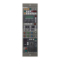
Using the adjustment remote commander and service modes for calibration.

SECTION 6 REPAIR PARTS LIST

Exploded Views of Parts

Visual diagrams of disassembled parts for easy identification.

Electrical Parts List

Comprehensive list of all electrical components with specifications.

CAMERA COLOR REPRODUCTION ADJUSTMENT DIAGRAM

PARTS REFERENCE SHEETS

Board Component Location Diagrams

Diagrams showing component placement on DD-106, VC-206, and VI-148 boards.

Related product manuals