DCR-TRV9/TRV9E
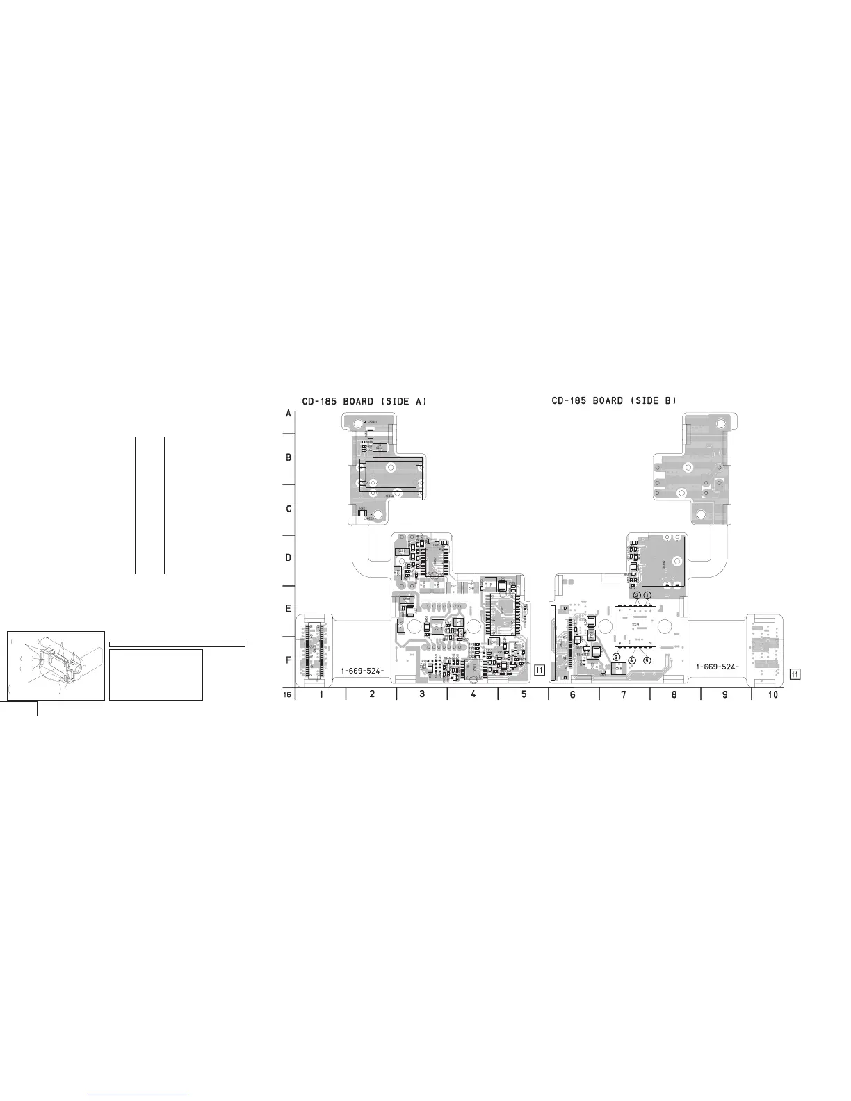
CD-185 (CCD IMAGER) PRINTED WIRING BOARD
— Ref. No.: CD-185 Board; 1,000 Series —
4-5 4-6 4-7 4-8
CCD IMAGER
CD-185
FP-676
HEADPHONE LANC
S/S SWITCH
DD-106
POWER
SUPPLY
VC-206
CAMERA, VIDEO IN/OUT, BLOCKING,
ECC, TBC, CHCO, AUDIO PROCESS,
RF INTERFACE, REC/PB HEAD AMP,
DV PROCESS, SERVO, HI CONTROL
FP-647
(VIDEO AUDIO IN/OUT)
VI-148
(Except AEP, UK model)
(VIDEO INTERFACE)
CD-185
(CCD IMAGER)
FK-4580
(VTR FUNCTION SWITCH)
PS4580
POWER
SWITCH
CD-185 BOARD
C302 E-6
C303 F-4
C304 E-5
C305 F-3
C306 E-5
C307 F-4
C308 F-5
C309 E-5
C310 F-4
C311 F-3
C312 F-3
C313 E-4
C314 D-4
C315 F-3
C316 F-5
C317 F-5
C318 F-7
C319 F-3
C320 F-6
C321 F-7
C323 F-4
C451 E-3
C452 E-3
C453 E-3
C455 F-3
C456 E-4
C458 F-4
C650 D-3
C651 D-7
C652 D-3
C653 B-2
C654 D-3
C655 D-3
C660 D-3
C661 E-4
C666 D-7
C667 E-3
C668 E-3
C669 D-7
C670 D-3
C671 D-3
C672 D-3
C677 E-4
C678 D-3
CN451 F-1
CN452 F-6
D301 F-6
IC301 F-4
IC302 E-5
IC651 F-3
L302 D-5
L303 F-4
L305 F-6
L451 E-4
L602 E-3
Q301 F-5
Q302 F-6
Q303 F-4
Q304 F-5
Q451 E-4
R301 E-5
R302 E-6
R303 F-5
R304 F-5
R305 F-5
R307 F-5
R308 F-6
R310 F-4
R311 F-4
R312 F-4
R313 F-4
R314 F-5
R315 F-4
R316 F-5
R317 F-4
R318 F-3
R319 F-4
R320 F-3
R321 F-3
R322 F-3
R323 F-4
R324 F-5
R325 F-4
R326 F-4
R327 F-4
R328 F-4
R329 F-3
R452 E-4
R454 F-4
R650 D-3
R651 D-7
R652 D-3
R653 D-7
R654 B-2
R655 C-2
R656 B-2
R664 D-3
R665 D-3
R666 D-7
R667 D-7
R669 D-7
R670 D-3
R671 D-3
R672 D-7
R673 D-3
Precautions Upon Replacing CCD Imager
• The CD-185 board mounted as a repair part is not equipped
with a CCD imager.
When replacing this board, remove the CCD imager from the
old one and mount it onto the new one.
• If the CCD imager has been replaced, carry out all the
adjustments for the camera section.
• As the CCD imager may be damaged by static electricity from
its structure, handle it carefully like for the MOS IC.
In addition, ensure that the receiver is not covered with dusts
nor exposed to strong light.
There are few cases that the part printed on this diagram isn’t mounted in this model.