EasyManua.ls Logo

Sony SA-SS-MS5 - User Manual

Sony SA-SS-MS5
14 pages
Print Icon
To Next Page IconTo Next Page
Loading...
MICROFILM
SERVICE MANUAL
MICRO SATELLITE SYSTEM
US Model
Canadian Model
AEP Model
UK Model
E Model
SPECIFICATIONS
SA-VE502/VE505/
WMS5/SS-MS5
The SA-VE502 system consists of one unit
of SA-WMS5 and two units of SS-MS5.
The SA-VE505 system consists of one unit
of SA-WMS5 and five units of SS-MS5.
Photo: SA-WMS5 Photo: SS-MS5
Question and Answer IconNeed help?

Do you have a question about the Sony SA-SS-MS5 and is the answer not in the manual?

Summary

Product Specifications

Audio Power Specifications

Details on power output and total harmonic distortion for the US model.

SS-MS5 (Front, Center, Rear Speakers) Specifications

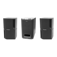
Specifications for the SS-MS5 satellite speakers, including impedance and frequency range.

SA-WMS5 (Subwoofer) Specifications

Specifications for the SA-WMS5 subwoofer, including type, output, and frequency range.

Safety Check-out and Leakage Test

Leakage Test Procedure

Methodology for testing AC leakage from exposed metal parts to earth ground.

Safety-Related Component Warning

Warning about critical safety components identified by marks on diagrams and parts lists.

Section 1: General Information

SA-WMS5 Control Layout

Front and rear view of the SA-WMS5 showing control knob locations and input/output terminals.

Section 2: Diagrams and Notes

Notes for Printed Wiring Boards and Schematic Diagrams

Explanation of symbols, notations, and abbreviations used in schematic diagrams.

Circuit Board Locations

Diagram showing the location of circuit boards within the SA-WMS5 unit.

Section 2: Printed Wiring Boards

Power Board Layout

Printed wiring board layout for the Power Board.

Main Board Layout

Printed wiring board layout for the Main Board.

Section 2: Component Locations and Board Layouts

Semiconductor Locations

Lists of semiconductor component locations for Main and Auto Power Boards.

Board Layouts

Layouts for Control, Power Switch, Auto Power, and LED Boards.

Section 2: Schematic Diagrams

Main Board Schematic

Detailed schematic diagram for the Main Board.

Power, Control, Auto Power, LED Board Schematics

Schematic diagrams for Power, Control, Auto Power, and LED Boards.

Section 2: IC Block Diagrams

Main Board IC Block Diagrams

Block diagrams for integrated circuits on the Main Board.

Auto Power & Control Board IC Block Diagrams

Block diagrams for integrated circuits on the Auto Power and Control Boards.

Section 3: Exploded Views

Front Panel Section (SA-WMS5)

Exploded view of the front panel assembly for the SA-WMS5.

Section 3: Exploded Views (SA-WMS5 Amplifier)

Amplifier Section (SA-WMS5)

Exploded view of the amplifier section for the SA-WMS5.

Section 3: Exploded Views (SS-MS5)

SS-MS5 Exploded View

Exploded view of the SS-MS5 speaker assembly.

Section 4: Electrical Parts List

Auto Power Control Board Parts

List of electrical components for the Auto Power Control Board.

Section 4: Electrical Parts List (Control & Main)

Control and Main Board Parts

List of electrical components for the Control and Main Boards.

Section 4: Electrical Parts List (Main Power)

Main Power Board Parts

List of electrical components for the Main Power Board.

Section 4: Electrical Parts List (Power Switch & Hardware)

Power Switch Board Parts & Hardware

List of components for the Power Switch Board and hardware items.

Sony SA-SS-MS5 Specifications

General IconGeneral
BrandSony
ModelSA-SS-MS5
CategoryMicro Music System
LanguageEnglish

Related product manuals