Do you have a question about the Sony SA-WA10R and is the answer not in the manual?
Details power output and total harmonic distortion for US model.
Specifications for DIN and continuous RMS power output.
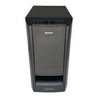
Speaker system details, including woofer type and rated impedance.
Power requirements, consumption, dimensions, and mass.
Information on a specific jig required for speaker removal.
Precautions for replacing chip components, especially tantalum capacitors.
Procedure for safety checks, including AC leakage measurement methods.
Warning about critical safety components identified in diagrams and parts lists.
Characteristics and handling of unleaded solder and the lead-free mark.
Steps for confirming operation, including necessary units for ATS-SW10Ti/SA-WA10R.
Guidance on obtaining remote commanders and installing specific parts like EZW-RT10A.
Procedure for safely discharging capacitors to prevent electric shock.
Specific instruction that IC602 on the MAIN (SW) board cannot be exchanged individually.
A step-by-step flowchart illustrating the disassembly order of the set.
Detailed instructions and diagrams for disassembling the front panel section.
Instructions and diagrams for removing the chassis assembly.
Steps and diagrams for disassembling the rear panel components.
Instructions for removing the power supply board.
Steps for removing the main circuit board.
Steps to perform a cold reset on the system.
Steps to check the system version using LED indicators.
Overall system block diagram showing signal paths and component interconnections.
Detailed circuit schematic for the Panel (SW) board.
Layout diagrams for the printed circuit board traces of the Main (SW) board.
Part one of the circuit schematic for the Main (SW) board.
Part two of the circuit schematic for the Main (SW) board.
Circuit schematic for the Power (SW) board.
Layout diagrams for the printed circuit board traces of the Power (SW) board.
Functional block diagrams for key integrated circuits used in the system.
Detailed pin functions for the System Controller IC (IC602).
Detailed pin functions for the Power Control IC (IC01).
Diagram showing the assembly of the front panel components with part numbers.
Diagram showing the assembly of the rear panel components with part numbers.
Comprehensive list of capacitors with part numbers, types, values, and tolerances.
Comprehensive list of resistors with part numbers, values, and tolerances.
List of semiconductors (diodes, transistors, ICs) with part numbers.
List of coils, connectors, switches, and miscellaneous parts with part numbers.
Record of document revisions, including version, date, and description of changes.
| Frequency Response | 28 Hz - 200 Hz |
|---|---|
| Speaker Type | Bass Reflex |
| Phase Switch | Yes |
| Crossover Frequency | 50 Hz - 200 Hz |
| Auto Standby | Yes |
| Type | Subwoofer |