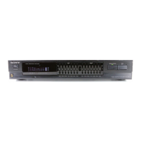
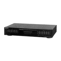
The Sony SB-V500 is a video/audio selector designed to manage and route multiple video and audio signals, offering flexibility for dubbing and monitoring. It features a robust set of input and output options, catering to both composite video and S-video signals, along with stereo audio. The device is primarily intended for users who need to connect and switch between several video sources, such as VTRs, video cameras, and disc players, and route their signals to various displays or recording devices.
Function Description
The core function of the SB-V500 is to act as a central hub for video and audio signal management. It allows users to select one of four input sources and route that signal to multiple outputs simultaneously. This capability is particularly useful for dubbing, where a single source can be recorded onto several VTRs at once.
The selector supports both composite video and S-video signals. A notable feature is its automatic Y/C separation circuit: a composite video signal input to the unit is automatically transformed into a Y/C separated S-video signal when output, though a composite signal is also simultaneously output. This ensures optimal picture quality, as the Y (luminance) and C (color) signals are kept separate, preventing interference and degradation often seen with composite signals.
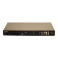
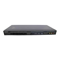
The device includes two sets of IN/OUT 4 jacks: one on the front panel and another at the rear. The front jacks are designed for temporary connections, such as a video camera recorder, allowing for easy plug-and-play. The signal introduced via the IN 4 jacks can be issued from the OUT 4 jacks, as well as from OUT 1, 2, and 3 jacks. This expands dubbing capabilities, allowing a video player connected to IN 4 to be recorded onto up to five different VTRs simultaneously.
The SB-V500 offers two output modes for the OUT 4 jacks, selectable via the OUTPUT MODE selector on the front panel:
- Mode A: In this mode, no signal is output from the OUT 4 jacks when IN 4 is selected by the INPUT SELECT switch. This is the normal operating mode. If a video player (for playback only) is connected to the IN 4 jacks, the OUT 4 jacks will remain unused.
- Mode B: When IN 4 is selected, the signal input via the IN 4 jacks is output from the OUT 4 jacks, as well as from OUT 1, 2, and 3 jacks. This mode is ideal for dubbing onto five different VTRs or connecting a secondary monitor to the OUT 4 jacks. A cautionary note advises setting the OUTPUT MODE selector to Mode A if a VTR or other equipment is connected to both IN 4 and OUT 4 jacks, to prevent oscillation when the VTR is set to recording mode.
The unit also features a MONITOR OUT EURO-AV connector (21-pin) for connecting to a color monitor, along with dedicated AUDIO R/L output jacks for connecting to audio equipment like a cassette deck or HiFi system.
Important Technical Specifications
- S-Video Output (4-pin mini DIN):
- Y signal: 1 Vp-p, 75 ohms unbalanced, sync negative
- C signal (burst signal): 0.286 Vp-p, 75 ohms unbalanced
- Video Inputs (phono jack)/Outputs (phono jack/21-pin):
- Reference signal input: 1.0 Vp-p
- Output level: 1.0 Vp-p (75 ohms terminated)
- Impedance: 75 ohms
- Sync: Negative
- Signal-to-noise ratio: More than 48 dB
- Crosstalk: More than 45 dB (3.58 MHz)
- Audio Inputs/Outputs:
- Reference signal input: -7.5 dBs
- Gain: 0 dB
- Input impedance: More than 47 kilohms
- Output impedance: Less than 5 kilohms
- Signal-to-noise ratio: More than 80 dB
- Separation: More than 80 dB
- Crosstalk: More than 80 dB
- Power Requirements:
- United Kingdom: 240 V AC, 50 Hz
- European countries: 220 V AC, 50 Hz
- Power Consumption: 14 W (for both UK and European models)
- Dimensions (w/h/d): 430 x 55 x 329 mm (17 x 2 1/8 x 13 inches)
- Weight: Approx. 3.7 kg (8 lb 3 oz)
- Remote Commander RMT-520:
- Power requirements: 3 V DC
- Dimensions: 51 x 20 x 175 mm (2 1/8 x 13/16 x 7 inches)
- Weight: Approx. 55 g (2 oz), not including batteries
Usage Features
- Input Select Switches: Allow selection of the desired input signal. The selected signal is then routed to the monitor output and other non-corresponding output jacks (in Mode A).
- Output Mode Selector: Toggles between Mode A and Mode B for the OUT 4 jacks, providing flexibility for different dubbing and monitoring setups.
- Front/Rear Input 4 Selector: Enables switching between the front and rear IN 4 jacks, indicated by an LED. This is convenient for frequently connecting/disconnecting devices.
- AUTO Y/C SEPARATE Indicator: Lights up when the output signal is automatically converted to a Y/C separated S-video signal, confirming optimal signal processing.
- MUTING Switch: Temporarily mutes video or audio output to the monitor, useful for quick interruptions without disconnecting cables.
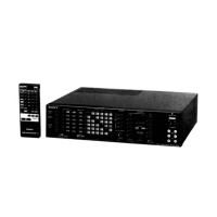
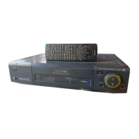
- Remote Commander RMT-520: Provides convenient remote control for power on/off (standby mode), input selection, and muting. It uses two SUM-3(NS) (AA size) batteries, with an expected life of about six months under normal operation.
- Power Switch: Turns the unit on or sets it to standby mode when the main unit's power switch is on.
- Standby Indicator: Illuminates when the unit is in standby mode, controlled by the remote commander.
- Video/S Video Selector: Allows selection between S-VIDEO and VIDEO output signals, depending on the connected monitor's capabilities.
Maintenance Features
The service manual includes a "Safety Check-Out" section, emphasizing critical steps after any repair to ensure the device's safe operation before returning it to the customer. These checks include:
- Solder Joint Inspection: Verifying for unsoldered or poorly-soldered connections, as well as solder splashes and bridges on the board surface.
- Wiring Integrity: Ensuring that interboard wiring is not "pinched" or in contact with high-wattage resistors.
- Component Verification: Checking for unauthorized replacement parts, particularly transistors, and recommending their replacement if found.
- Deterioration Check: Identifying any parts showing obvious signs of deterioration, even if functioning, and recommending their replacement.
- B+ Voltage Check: Confirming that the B+ voltage is at specified values.
The manual also highlights "Safety-Related Components" identified by specific marks on schematic diagrams and parts lists. These components are critical for safe operation and must be replaced only with genuine Sony parts.
For the remote commander, maintenance notes advise:
- Keeping it away from extremely hot or humid places.
- Avoiding dropping foreign objects into the casing, especially during battery replacement.
- Not simultaneously depressing two or more buttons to prevent malfunctions.
- Avoiding exposure of the remote sensor to direct sunlight or strong lighting, which can cause malfunctions.
The device's design and specifications are subject to change without notice, as stated in the manual.