EasyManua.ls Logo

Sony SB-V3000 Service Manual

Sony SB-V3000
79 pages
To Next Page IconTo Next Page
Page #1 background imageLoading...
Page #1 background image
SERVICE
MANUAL
-
-
ai
saa
*
Service
of
remote
commander
RMT-3000.
*
Remote
commander
RMT-3000
is
available
as
a
unit.
But
as
indivdual
parts
the
battery
case
lid
of
commander
is
only
available.
SPECIFICATIONS
Inputs/outputs
Audio
outputs
(10)
P F
Jack
type
Phono
jack/21-pin
connector
oo
(8)
sean
Output
impedance
Less
than
5
kilohms
Y
signal
1
Vp-p,
75
ohms
unbalanced
(when
oan
ae
eee
te
cttee
terminated),
sync
negative
;
C
signal
(burst
signal)
0.286
Vp-p,
75
ohms
unbalanced
(when
a
nari
alg
He
ol
=
uneNee
Crosstalk
More
than
80
dB
S
video
outputs
(9)
2
Jack
type
4-pin
mini
DIN
ae
2
se
Pani
Y
signal
1
Vp-p,
75
ohms
unbalanced
(when
AEB
NDS:
Ree
terminated),
sync
negative
C
signal
(burst
signal)
0.286
Vp-p,
75
ohms
unbalanced
(when
Others
terminated)
Power
requirements
220
V
AC,
50
Hz
Power
consumption
44
W
(5.5
W
during
idling)
Video
inputs
(8)
Dimensions
430
x
115
x
370
mm
(w/h/d)
Jack
type
Phono
jack
(17
x
4
%/a
x
14
°/s
inches)
Reference
signal
input
1.0
Vp-p,
75
ohms
unbalanced
(when
Weight
Approx.
7.1
kg
(15
Ib.
10
oz.)
terminated)
Accessories
supplied
©
Remote
commander
RMT-3000
(1)
Sync
Negative
Sony
SUM-3(NS)
batteries
(2)
Labels
for
input/output
selection
(1
set)
Video
outputs
(10)
Jack
type
Phono
jack/21-pin
connector
Remote
commander
RMT-3000
Output
level
1.0
Vp-p,
75
ohms
unbalanced
(when
Remote
control
system
Infrared
control
terminated)
Power
requirements
3
VDC
Sync
Negative
Dimensions
67
x
20
x
176
mm
(w/h/d)
Signal-to-noise
ratio
More
than
48
dB
(2
%/¢
x
3/16
x
7
inches)
Crosstalk
More
than
45
dB
(3.58
MHz)
Weight
Approx.
110
g
(4
02.)
not
including
batteries
Audio
inputs
(9)
Jack
type
Phono
jack
Design
and
specifications
are
subject
to
change
without
notice.
Reference
signal
input
-7.5
dB
Input
capacity
2.0
Vrms
Input
impedance
More
than
47
kilohms
VIDEO
/AUDIO
SELECTOR
SONY.
MICROFILM
Question and Answer IconNeed help?

Do you have a question about the Sony SB-V3000 and is the answer not in the manual?

Sony SB-V3000 Specifications

General IconGeneral
BrandSony
ModelSB-V3000
CategoryRecording Equipment
LanguageEnglish

Summary

Service Manual

Specifications Overview

Details on input/output, audio, control S, and other specifications.

General Information

1-1. Outline and Capabilities

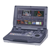
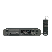
Describes the unit's features and various equipment connectivity.

1-2. Control Locations and Functions

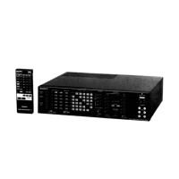
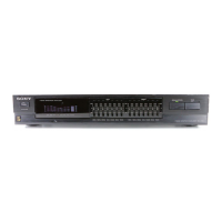
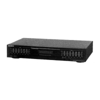
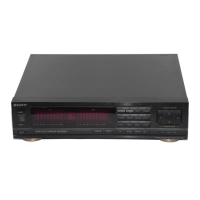
Details front panel controls, indicators, and their operations.

Rear Panel and Remote Commander

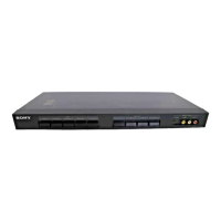
Identifies rear panel connectors and remote commander functions.

Connection Procedures

Guides for connecting monitors and other video equipment.

Connecting External Equipment

Instructions for connecting VTRs, video players, AV processors, and audio systems.

Monitoring and Editing Operations

Procedures for monitoring video signals and performing editing tasks.

1-10. Memorizing Input/Output Settings

How to save and recall input/output configurations.

1-11. Using the Remote Commander

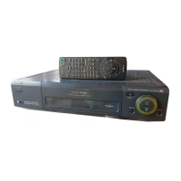
Detailed operation guide for the supplied remote commander.

1-12. Connecting the PCM Audio Processor

Instructions for connecting a PCM audio processor.

Disassembly

Section 2 Disassembly Procedure

Step-by-step instructions for safely disassembling the unit.

Diagrams

3-1. Circuit Board Location

Diagram showing the placement of internal circuit boards.

3-2. Overall Block Diagram

High-level block diagram of the system's architecture.

3-3. Video I/O, Composite, Y Block Diagram

Detailed block diagram for video input/output and signal processing.

3-4. Video I/O, Parallel Series Converter Diagram

Diagram illustrating video signal conversion processes.

3-5. Audio, Video Control, Chroma Block Diagram

Block diagram for audio, video control, and chroma signal paths.

3-6. Power Block Diagram

Block diagram of the unit's power supply system.

3-7. System Control Block Diagram

Block diagram detailing the system control logic.

3-8. System Control (KS-5 Board IC401)

Specific details of the KS-5 board IC401 and its pins.

Printed Wiring Boards and Schematic Diagrams

4-1. Frame Schematic Diagram

Overall schematic diagram for the main frame.

4-2. Printed Wiring Boards and Schematic Diagrams

General notes for interpreting PWB and schematic diagrams.

CY-5 (S VIDEO) Printed Wiring Board

PWB layout for the CY-5 S VIDEO board.

FT-40, FY-4 Printed Wiring Boards

PWB layouts for FT-40 and FY-4 terminal boards.

CE-11 Printed Wiring Boards

PWB layout for the CE-11 board.

CA-26 Printed Wiring Board

PWB layout for the CA-26 audio, video control board.

PW-65 (POWER) Printed Wiring Board

PWB layout for the PW-65 power supply board.

FD-11, PD-20 Printed Wiring Boards

PWB layouts for FD-11 and PD-20 boards.

KS-5 Printed Wiring Board

PWB layout for the KS-5 control switch and display board.

Exploded Views

5-1. Front Panel, Cabinet Assembly

Exploded view of the unit's front panel and cabinet.

5-2. Boards and Chassis Section

Exploded view of internal boards and chassis components.

Electrical Adjustments

7-1. Confirmation of Input Signal

Procedures for confirming input signal levels and waveforms.

7-1-1. Adjustment of YC Separation Level

Specific adjustment procedure for YC separation on the CY-5 board.

7-2. Adjustment Related Parts Location

Identifies the location of components related to adjustments.

Related product manuals