6-9
(2) Linearity adjustment (Guide roller S, T adjustment)
1) Playback the Mono Scope alignment tape (SP mode).
2) Observe the video envelope signal on an oscilloscope (triggered by the video switching pulse).
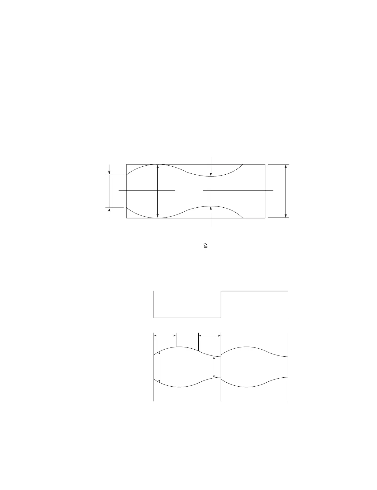
3) Make sure the video envelope waveform (at its minimum) meets the specification shown in Fig. 6-11.
If it does not, adjust as follows :
Note:
a=Maximum output of the video RF envelope.
b=Minimum output of the video RF envelope at the entrance side.
c=Minimum output of the video RF envelope at the center point.
d=Maximum output of the video RF envelope at the exit side.
4) If the section A in Fig. 6-12 does not meet the specification, adjust the guide roller S up or down.
5) If the section B in Fig. 6-12 does not meet the specification, adjust the guide roller T up or down.
a
a b c d
c,b,d/a
63%
b
c
d
Fig. 6-11 Envelope Waveform Adjustment
AB
A B
H'D SWITCHING PULSE
ENVELOPE
Fig. 6-12 Adjustment Points