AEP Model
SLV-SE10AE1/SE10AE2
UK Model
SLV-SE20UX/SE30UX/SE45UX
French Model
SLV-SE25B/SE40B
German Model
SLV-SE20VP1/SE20VP2/SE25VC
/SE30VC1/SE30VC2/SE40VC1
/SE40VC2/SE45VC/SX25VC
Spanish Model
SLV-SE25CP/SE30CP/SE40CP/SE45CP
East European Model
Greek Model
SLV-SE10EE/SE10EG/SE30EE/SE40EE/
SE40EG/SX10EG/SX40EG
Irish Model
SLV-SE20EX
SERVICE MANUAL
VIDEO CASSETTE RECORDER
MICROFILM
SLV-SE10/SE20/SE25/SE30/SE40/SE45/SX10/SX25/SX40
RMT-V256/V256A/V257/V257A/V257B/V257C/V259
j
Refer to the SERVICE MANUAL of VHS
MECHANICAL ADJUSTMENT
for
MECHANICAL ADJUSTMENTS. (9-921-647-11)
SPECIFICATIONS
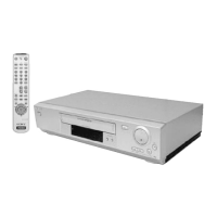
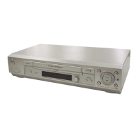
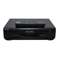
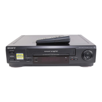
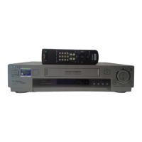
Photo: SLV-SE45
RMT-V259
S MECHANISM
System
Channel coverage(10EE/EG/30EE/40EE/EG/
X10/X40 MODEL)
PAL(B/G,D/K):
VHF E2 to E12,R1 to R12
UHF E21 to E69,R21 to R69
CATV S1 to S41,S01 to S05
PAL(B/G):(10AE1/AE2/40B/25B/45CP/
30CP/VC1/VC2/20VP1/VP2/25CP/VC/40CP/
VC1/VC2/45VC/X25 MODEL)
VHF E2 to E12
VHF Italian channels A to H
UHF E21 to E69
CATV S01 to S05,S1 to S20
HYPER S21 to S41
SECAM(L):(SE25B/40B MODEL)
VHF F2 to F10
UHF F21 to F69
CATV B to Q
HYPER S21 to S41
PAL(B/G):
VHF E2 to E12
VHF Italian channels A to H
UHF E21 to E69
CATV S01 to S05,S1 to S20
HYPER S21 to S41
PAL (I)(20EX/UX MODEL)
VHFIA to IJ,SA10 to SA13(20EX only)
UHF B21 to B69
CATV S01 to S05,S1 to S20(20EX only)
HYPER S21 to S41
PAL (I)(SE30UX/45UX MODEL)
UHF B21 to B69
RF output signal
UHF channels 21 to 69
Aerial out
75-ohm asymmetrical aerial socket
Inputs and outputs
LINE-1
(TV)
21-pin
Video input: pin 20
Audio input: pins 2 and 6
Video output: pin 19
Audio output: pins 1 and 3
LINE-2 IN(10EE/30CP/VC1/VC2/EE/UX/
45CP/UX MODEL)
VIDEO IN, phono jack (1)
Input signal: 1 Vp-p,
75 ohms, unbalanced,sync negative
AUDIO IN,
phono jack (1)
Input level: 327 mVrms
Input impedance : more than 47 kilohms
LINE-2 IN(SE25VC/40VC1 MODEL)
21-pin
Video input: pin 20
Audio input: pins 2 and 6
LINE-2 IN
(25B/CP/VC/UX/40B/CP/VC1/VC2/45VC/
UX/X25 MODEL)
LINE-3 IN
(30CP/VC1/UX/VC2/45CP/UX)
21-pin
Video input: pin 20
Audio input: pins 2 and 6
LINE OUT(10EE/30EE/40EE)
AUDIO OUT,Phono jack(2)
Rated output level:327mVrms
Load impedance:47 kilohms
Output impedance:less than 10 kilohms
VIDEO OUT,Phono jack(1)
Rated output level:327mVrms
Load impedance:47 kilohms
Output impedance:less than 10 kilohms
General
Power requirements
220 - 240 V AC, 50 Hz
Power consumption
22 W
Operating temperature
5°C to 40°C
Storage temperatur
-20°C to 60°C
Dimensions
Approx. 355 x 96 x 285 mm(w/h/d)
including projecting parts and controls
Mass
Approx. 3.8 kg
(Approx. 10 lb 2 oz)
Supplied accessories
Remote commander (1)
R6 (size AA) batteries (2)
Aerial cable (1)
AC Plug adaptor(1)(20EX/UX)
Design and specifications are subject to change without
notice.
w
w
w
.
x
i
a
o
y
u
1
6
3
.
c
o
m
Q
Q
3
7
6
3
1
5
1
5
0
9
9
2
8
9
4
2
9
8
T
E
L
1
3
9
4
2
2
9
6
5
1
3
9
9
2
8
9
4
2
9
8
0
5
1
5
1
3
6
7
3
Q
Q
TEL 13942296513 QQ 376315150 892498299
TEL 13942296513 QQ 376315150 892498299
http://www.xiaoyu163.com
http://www.xiaoyu163.com