Do you have a question about the Sony SLV-SF900 and is the answer not in the manual?
Detailed technical specifications of the VCR models including channel coverage and tape speed.
Procedure for performing safety checks after correcting the original service problem.
Guidance on resolving common operational issues and problems.
Detailed schematics and printed wiring boards for various VCR sections.
Pin function description for the system control to video block interface.
Pin function description for system control to servo peripheral circuit interface.
Detailed pin function mapping for the Servo/System Control microprocessor.
Detailed pin function mapping for the Mode Control microprocessor.
Detailed pin function mapping for the Smart File Control microprocessor.
Detailed pin function mapping for the Smart File Teletext microcomputer.
Instructions for performing mechanical adjustments of the VCR.
Procedures for performing electrical adjustments and calibration.
Explanation of error codes indicated on the fluorescent display tube.
Procedure for inputting data into the EEPROM after replacement.
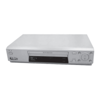
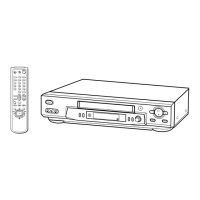
Step-by-step guide for initial VCR setup, including unpacking and connections.
Detailed steps for setting the VCR's clock.
Step-by-step guide for recording TV programs.
Step-by-step guide for recording TV programs.
First part of the overall system block diagram.
First part of the video block diagram.
Second part of the video block diagram.
First part of the servo/system control block diagram.
Second part of the servo/system control block diagram.
Block diagram illustrating the audio processing system.
Block diagram of the Smart File system.
First part of the power block diagram.
Second part of the power block diagram.
Overall schematic diagram showing the VCR's frame and main connections.
Schematic for the Record/Playback Head Amplifier circuit.
Schematic for the Record/Playback Head Amplifier circuit.
Schematic for the Y/C and Audio Processor circuit.
Schematic for the On Screen Display circuit.
Schematic for the Servo/System Control circuit.
Schematic for the Input/Output circuit.
Schematic for the Audio circuit.
Schematic for the Tuner circuit.
Schematic for the Power Supply circuit.
Printed wiring board schematic for the RP-238 (Bias) board.
Schematic diagram for the RP-238 (Bias) board.
Printed wiring board schematic for the FR-169 Indicator board.
Schematic diagram for the FR-169 Indicator board.
Schematic showing user functions on the DM-95 board.
Printed wiring board schematic for the DM-95 User Function.
Printed wiring board schematic for the SE-109 Secam Signal Process board.
Schematic diagram for the SE-109 Secam Signal Process board.
Printed wiring board schematic for the ML-21 Smart File board.
Printed wiring board schematic for the AT-28 Large Antenna board.
First part of the ML-21 board schematic.
Second part of the ML-21 board schematic.
Printed wiring board schematic for the JK-195 Line 2 In board.
Printed wiring board schematic for the Power Block (SRV939EK).
Schematic diagram for the Power Block (SRV939EK).
Detailed pin function mapping for the Smart File Teletext microcomputer.
Procedures for performing electrical adjustments and calibration.
Procedure for checking the power supply voltages on the MA-388 board.
Exploded views showing VCR parts for identification.
| Type | VCR |
|---|---|
| Video Format | VHS |
| Recording Speed | SP, LP, EP |
| Playback Speed | SP, LP, EP |
| Playback Head | 4-Head |
| Dimensions | 17 x 3.9 x 13.8 inches |
| Weight | 9.9 lbs |
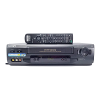
| Remote Control | Yes |
| Hi-Fi Stereo | Yes |
| Tuner | Yes |
| Inputs | Composite video |
| Outputs | Composite video |