Do you have a question about the Sony SLV-SF90 and is the answer not in the manual?
Details technical specifications for the VCR, including system, input/output, general parameters, and accessories.
Lists different model designations like UK, French, German, Spanish, E, and Irish models.
Covers system, input/output, general VCR parameters, and supplied accessories.
Alerts to critical safety components identified by marks, requiring specific replacement parts.
Explains how error codes and encoder data are displayed in MECHA emergency mode.
Guides through initial setup, basic/additional operations, and SmartFile function.
Includes troubleshooting guides and index to parts.
Step-by-step guides for disassembling VCR components like case, boards, and mechanism.
Detailed block diagrams for VCR systems including video, servo, memory, audio, and power.
Important notes regarding interpreting printed wiring boards and schematic diagrams.
Overall schematic diagram showing major functional blocks and interconnections.
Detailed schematics and PWB layouts for the MA-359 board, covering various functions.
Schematics and PWB layouts for the RP-235 board, used for REC/PB head amp.
Schematics and PWB layouts for the JK-171 board, handling Line 2 input.
Schematics and PWB layouts for the DM-86 board, used for user control.
Schematics and PWB layouts for the FR-161 board, handling mode and FL drive.
Schematics and PWB layouts for the SE-90 board, covering SECAM chroma process.
Schematics and PWB layouts for the NR-27 board, related to DNR and Y/C selection.
Schematics and PWB layouts for the SRV879EK power supply board.
Schematics and PWB layouts for ML-17, AT-25, and AT-26 boards related to Smart File and sensors.
Detailed pin assignments and functions for ICs in video, servo, mechanism, and audio interfaces.
Pin functions for the servo/system control microprocessor on the MA-359 board.
Pin functions for tuner and timer mode control on the FR-161 board.
Procedures for mechanical adjustments and preparation for electrical adjustments.
Checks for power supply voltages and procedures for servo system adjustments.
Checks for playback level, sync AGC, and deviation of video signals.
Adjustments for DNR Y/C levels and Hi-Fi/normal audio system characteristics.
Normal audio system adjustments and frequency response checks.
Visual breakdowns of the VCR's sections with corresponding part numbers.
A comprehensive list of electrical components, including part numbers and descriptions.
Explains how error codes and encoder data are displayed in MECHA emergency mode.
Lists various function modes and their corresponding codes for VTR operations.
Guides through initial setup steps, including unpacking and connecting the VCR.
Covers fundamental VCR functions like playing and recording tapes.
Guide on setting up and using the remote commander for TV control.
Instructions for connecting the VCR to a TV using different cable types.
Guide to automatically setting up the VCR, including language and country selection.
Instructions for setting the VCR's internal clock accurately.
Guide for setting up the VCR to receive satellite channels.
How to select the on-screen display language for the VCR.
Instructions for manually setting and storing TV channels.
How to assign custom names to TV channels for easier identification.
How to reorder or disable programmed channels.
Guide for connecting and setting up a PAY-TV or Canal Plus decoder.
Instructions on how to insert and play a VHS tape.
Further steps and tips for playing VHS tapes.
Guide on how to record TV programs directly from the VCR.
Instructions for using the ShowView system to record TV programs.
How to manually set the VCR timer for recording specific programs.
How to play or search tapes at different speeds using controls.
Guide for recording programs with stereo or bilingual audio tracks.
How to manage, modify, or cancel programmed timer recordings.
Steps to adjust picture settings like sharpness and color.
How to connect and edit content with external VCRs or stereo systems.
How to dub audio from a stereo system to a VHS tape.
How to record programs directly using the SmartFile function.
How to view recorded program data using the SmartFile sensor.
How to select and play programs managed by the SmartFile function.
How to label recorded programs and tapes using the SmartFile feature.
Method to protect recorded programs from accidental erasure or damage.
A guide to diagnosing and resolving common VCR problems.
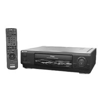
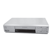
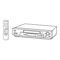
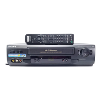
Identification and location of controls on the VCR's front panel.
Visual representation of the VCR's on-screen menu system and options.
Procedures for disassembling the VCR's case and front panel block.
Details disassembly steps for specific circuit boards.
Instructions for disassembling the VCR's rear panel section.
Steps for disassembling the NR-27 and RP-235 boards.
Steps for disassembling the SR mechanism deck.
Procedures for disassembling the power block and MA-359 boards.
Diagrams showing internal components and their locations.
A diagram indicating the placement of various circuit boards within the VCR.
High-level block diagram showing the VCR's system architecture.
Detailed block diagram illustrating the video processing circuits, part 1.
Block diagrams explaining the servo control system, part 1.
Block diagram for the memory and SmartFile functions.
Detailed block diagram of the VCR's audio processing circuits.
Block diagram illustrating the power supply and distribution circuits, part 1.
Important notes regarding interpreting printed wiring boards and schematic diagrams.
Overall schematic diagram showing major functional blocks and interconnections.
Detailed schematics and PWB layouts for the MA-359 board, covering various functions.
Schematics and PWB layouts for the RP-235 board, used for REC/PB head amp.
Schematics and PWB layouts for the JK-171 board, handling Line 2 input.
Schematics and PWB layouts for the DM-86 board, used for user control.
Schematics and PWB layouts for the FR-161 board, handling mode and FL drive.
Schematics and PWB layouts for the SE-90 board, covering SECAM chroma process.
Schematics and PWB layouts for the NR-27 board, related to DNR and Y/C selection.
Schematics and PWB layouts for the SRV879EK power supply board.
Schematics and PWB layouts for ML-17, AT-25, and AT-26 boards related to Smart File and sensors.
Detailed pin assignments and functions for ICs in video, servo, mechanism, and audio interfaces.
Pin functions for the servo/system control microprocessor on the MA-359 board.
Pin functions for tuner and timer mode control on the FR-161 board.
Procedures for mechanical adjustments and preparation for electrical adjustments.
Checks for power supply voltages and procedures for servo system adjustments.
Checks for playback level, sync AGC, and deviation of video signals.
Adjustments for DNR Y/C levels and Hi-Fi/normal audio system characteristics.
Normal audio system adjustments and frequency response checks.
Visual breakdowns of the VCR's sections with corresponding part numbers.
A comprehensive list of electrical components, including part numbers and descriptions.
| Brand | Sony |
|---|---|
| Model | SLV-SF90 |
| Type | VCR |
| Video Format | VHS |
| Hi-Fi Stereo | Yes |
| Heads | 4 |
| Remote Control | Yes |
| Recording Speed | SP, LP |
| Playback Speeds | SP, LP |
| Connections | RF, Composite Video Output |
| Inputs | Composite video |
| Outputs | Composite video |