Installation
Caution
To prevent the camera from falling, make sure to attach the supplied wire
rope.
Suitable lens
The lens must be a CS-mount type and the protrusion behind the mounting
surface must be 5.5 mm (/ inch) or less.
Caution
When you install it into a wall or a ceiling, check that the wall or the ceiling ˎ
is strong enough to hold the weight of the camera including the mounting
bracket, and install it without fail. If not, the camera falls down and causes
a serious injury.
Also, check if the mounting is not loosened at least once a year. Make the
checking interval short according to use condition.
Performance will depend on the installation environment and the lens ˎ
itself. For details, contact your authorized Sony dealer.
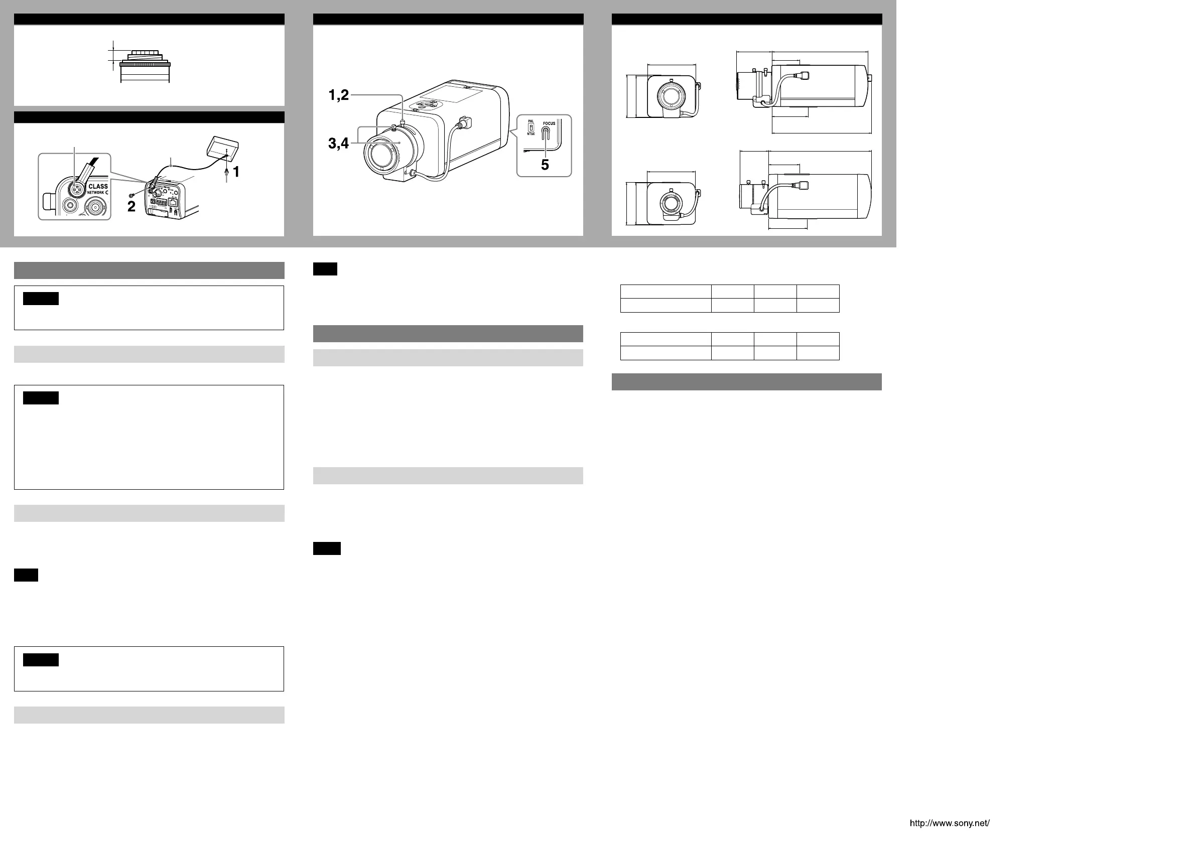
Attaching the wire rope
When you install the camera on a ceiling or a high position, be sure to attach the
supplied wire rope to prevent the camera from falling.
Attach the wire rope to the screw hole on the rear of the camera, as in the
illustration.
Note
Take care not to short-circuit the power terminal or the cable with the wire rope
when you attach it.
1 Secure the wire rope to the junction box on the ceiling.
Use a screw to match the screw hole of your junction box (not supplied).
2 Secure the wire rope to the wire rope mounting screw hole on the rear of
the camera using the supplied screw.
Caution
Use the supplied screws for installation. If not, the wire rope may not function
properly.
Adjusting the Camera Coverage and Focus
1
Loosen the zoom ring locking screw to adjust the camera shooting
coverage.
2 Tighten the locking screw to fix the zoom.
3 Loosen the focus ring locking screw to adjust the focus.
4 Tighten the locking screw to fix the focus ring.
5 Press the Easy Focus button on the rear to automatically adjust the focus
(except SNC-EB600B/EB630B).
Note
You may not achieve satisfactory focus with the Easy Focus button due to the
shooting environment.
In this case, press and hold the Easy Focus button for more than 4 seconds to
return to the default position. Then, adjust the focus following step 3 and 4.
Connection
Connecting to the Network
Connect the LAN connector of the camera to a PoE* supported device (such as a
hub) using the network cable (straight, not supplied).
The electrical power is supplied through the network cable. For details, refer to
the instruction manuals of the PoE supported devices.
(* PoE: The acronym for Power over Ethernet. IEEE802.3af standard compliant
devices.)
SNC-VB600/VB600B/VB630
It is also possible to connect the LAN port of the camera to a router or hub in the
network using a network cable (not supplied).
Connecting the Power Source
The camera can be powered in the following ways.
12 V DC or 24 V AC (Either voltage supported by SNC-VB600/VB600B/VB630 ˎ
only.)
Power supply equipment pursuant to IEEE802.3af (PoE* system) ˎ
* PoE stands for Power over Ethernet.
Notes
Do not turn off the camera immediately after turning it on. Wait for at least five ˎ
minutes before turning off the camera.
Do not connect the power input cable if power is supplied by a PoE system. ˎ
Connecting to the power supply equipment pursuant to IEEE802.3af
The power supply equipment pursuant to IEEE802.3af supplies the power
through the network cable. For details, refer to the Instruction Manual of the
equipment.
Connecting to 12 V DC or 24 V AC source
Connect the power input cable of the camera to a 12 V DC or 24 V AC source.
Use a 12 V DC or 24 V AC source isolated from 100 to 240 V AC. The acceptable ˎ
voltage ranges for each are as follows.
12 V DC: 10.8 V to 13.2 V
24 V AC: 19.2 V to 28.8 V
- In the USA, The product shall be powered by a UL Listed Class 2 Power
Supply Only.
- In Canada, The product shall be powered by a CSA certified Class 2 Power
Supply Only.
Use UL cable (VW-1 style 10368) for these connections. ˎ
Recommended cable
12 V DC:
CABLE(AWG) #24 #22 #20
Max. length(m(feet)) 8 (26.2) 14 (45.9) 20 (65.5)
24 V AC:
CABLE(AWG) #24 #22 #20
Max. length(m(feet)) 11 (36.1) 19 (62.3) 28 (91.9)
Specifications
Compression
Video compression format JPEG/H.264
Audio compression format G.711/G.726/AAC
Maximum frame rate SNC-VB600/VB630
60 fps
SNC-VB600B/EB600/EB600B/EB630/EB630B
30 fps
Camera
Signal system NTSC color system/PAL color system
(switchable)
Image device SNC-VB600/VB600B/EB600/EB600B
1/3type CMOS (Exmor)
Effective picture elements:
Approx. 1,370,000
SNC-VB630/EB630/EB630B
1/2.9type CMOS (Exmor)
Effective picture elements:
Approx. 2,140,000
Synchronization Internal synchronization
Horizontal resolution SNC-VB600/VB600B: 600 TV lines (analog video)
SNC-VB630: 700 TV lines (monitor display ratio
4:3)
Video S/N More than 50 dB (Auto gain control maximum
rate 0 dB)
Minimum illumination View-DR Off/VE* Off/Auto gain control
maximum rate MAX/50 IRE (IP)/30 fps
SNC-VB600/VB600B
F1.2/Color: 0.05 lx, Black & White: 0.04 lx
SNC-VB630/EB630/EB630B
F1.2/Color: 0.10 lx, Black & White: 0.07 lx
SNC-EB600/EB600B
F1.0/Color: 0.05 lx, Black & White: 0.04 lx
* VE stands for Visibility Enhancer.
Lens
Focal length SNC-VB600/VB600B/VB630/EB630/EB630B:
2.8 mm to 8 mm
SNC-EB600/EB600B: 3 mm to 8 mm
Maximum relative aperture SNC-VB600/VB600B/VB630/EB630/EB630B:
F1.2 to F1.95
SNC-EB600/EB600B: F1.0 to F1.65
C
CS-mount lens
5.5 (/) or less
Unit: mm (inch)
D
Screw (supplied)
Wire rope (supplied)
Screw (not supplied)
E
F
Front
Front
Side
SNC-VB600/VB600B/VB630/EB630/EB630B
SNC-EB600/EB600B
Side
145 (5 /)
44 (1 /)
55 (2 /)
54.1 (2 /)
150.5 (6) (SNC-VB600/
VB600B/VB630 only)
72 (2 /)
62 (2 /)
63 (2 /)
72 (2 /)
62 (2 /)
63 (2 /)
Unit: mm (inches)
145 (5 /)
44 (1 /)
55 (2 /)
42.8 (1 /)
View angle* SNC-VB600/VB600B: 1280 × 1024 (aspect ratio
5:4)
Vertical: 78.1° to 28.6°, Horizontal: 100.0° to
35.7°
SNC-VB630/EB630/EB630B: 1920 × 1080 (aspect
ratio 16:9)
Vertical: 60.6° to 22.5°, Horizontal: 114.2° to
40.0°
SNC-EB600/EB600B: 1280 × 1024 (aspect ratio
5:4)
Vertical: 72.7° to 28.6°, Horizontal: 92.5° to 35.7°
* The view angle will change, depending on the setting of the aspect ratio
resolution.
Minimum object distance SNC-VB600/VB600B/VB630/EB630/EB630B:
300 mm
SNC-EB600/EB600B: 200 mm
Interface (SNC-VB600/VB600B/VB630)
LAN (PoE) 10BASE-T/100BASE-TX, auto negotiation (RJ-45)
I/O port Sensor input: × 2, make contact, break contact
Alarm output: × 2, 24 V AC/DC, 1 A max.
(mechanical relay outputs electrically isolated
from the camera)
SD memory card slot
Video output VIDEO OUT: BNC, 1.0 Vp-p, 75 ohms,
unbalanced, sync negative
Microphone input* Minijack (monaural)
Plug-in-power supported (rated voltage: 2.5 V
DC)
Recommended load impedance: 2.2 k
Line input* Minijack (monaural)
* The microphone input and the line input are switchable with operating menu.
Line output Minijack (monaural), Maximum output level:
1 Vrms
Interface (SNC-EB600/EB600B/EB630/EB630B)
LAN (PoE) 10BASE-T/100BASE-TX, auto negotiation (RJ-45)
Video output Monitor output: 1.0 Vp-p, 75 ohms, unbalanced,
sync negative
AV minijack*
* Use an AV cable with a 4-pole AV mini plug.
Others
Power supply IEEE802.3af compliant (PoE system)
SNC-VB600/VB600B/VB630:
12 V DC ± 10%, 24 V AC ± 20%, 50 Hz/60 Hz
Power consumption SNC-VB600/VB600B/VB630: 6.0 W max.
SNC-EB600/EB600B/EB630/EB630B: 5.0 W max.
Operating temperature Start temperature: 0°C to 50°C (32°F to 122°F)
Working temperature: –10°C to +50°C
(14°F to 122°F)
Storage temperature –20°C to +60°C (–4°F to +140°F)
Operating humidity 20% to 80%
Storage humidity 20% to 95%
Dimensions (w/h/d)
72 mm × 63 mm × 145 mm (2
7
/8 inches ×
2
1
/2 inches × 5
3
/4 inches) not including the
projecting parts and lens
Mass SNC-VB600/VB600B/VB630: Approx. 565 g (1 lb
3.9 oz) with lens
SNC-EB600: Approx. 480 g (1 lb 0.9 oz) with lens
SNC-EB600B: Approx. 460 g (1 lb 0.2 oz) with
lens
SNC-EB630: Approx. 505 g (1 lb 1.8 oz) with lens
SNC-EB630B: Approx. 485 g (1 lb 1.1 oz) with
lens
Supplied accessories CD-ROM (Supplied programs) (1)
Wire rope (1)
Screw M4 (1)
Safety Regulations (1)
Installation Manual (this document) (1)
SNC-VB600/VB600B/VB630
DC 12 V/AC 24 V connector (1)
Design and specifications are subject to change without notice.
 Loading...