EasyManua.ls Logo

Sony SS-MS215 User Manual

Sony SS-MS215
10 pages
To Next Page IconTo Next Page
Page #1 background imageLoading...
Page #1 background image
AEP Model
UK Model
E Model
Australian Model
Chinese Model
SERVICE MANUAL
SPEAKER SYSTEM
SPECIFICATIONS
The SA-VE215 system consists of one unit
of SA-WMS215 and five units of SS-MS215.
This set is the Speaker section in HT-K170/
K215.
SA-VE215/WMS215/
SS-MS215
Photo: SA-WMS215
Photo: SS-MS215
SS-MS215 Front, center and rear speakers
Speaker system Full range, magnetically
shielded
Speaker units 5 cm cone type
Enclosure type Bass reflex
Rated impedance 8 ohms
Power handling 60 watts
capacity
(Maximum input
power)
Sensitivity level 84 dB (1W, 1m)
Frequency range 150 Hz - 20,000 Hz
Dimensions (w/h/d) Approx. 76 × 100 × 86 mm
including front grille
Mass Approx. 425 g
SA-WMS215 Subwoofer
System Active subwoofer,
Speaker system magnetically shielded
Speaker unit Woofer : 16 cm cone type
Enclosure type Acoustically Loaded Bass Reflex
Continuous RMS 50 W
power output
(8 ohms, 20 - 250 Hz)
Reproduction 32 Hz - 250 Hz
frequency range
High frequency 250 Hz
cut-off frequency
Input
LINE IN (input pin jack)
General
Power requirements 220 - 230 V AC, 50/60 Hz
Power consumptions 45 W
Dimensions (w/h/d) Approx. 240 × 285 × 355 mm
including front panel
Mass Approx. 8 kg
Design and specifications are subject to change without
notice
Ver 1.1 2003. 05
Sony Corporation
Home Audio Company
Published by Sony Engineering Corporation
9-929-500-12
2003E16-1
© 2003.05
Question and Answer IconNeed help?

Do you have a question about the Sony SS-MS215 and is the answer not in the manual?

Sony SS-MS215 Specifications

General IconGeneral
BrandSony
ModelSS-MS215
CategorySpeaker System
LanguageEnglish

Summary

Product Specifications

SS-MS215 Speaker Specifications

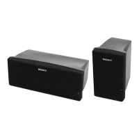
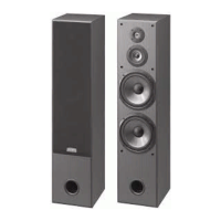
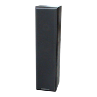
Detailed specifications for SS-MS215 front, center, and rear speakers.

SA-WMS215 Subwoofer Specifications

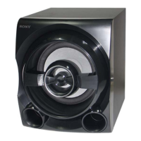
Technical specifications for the SA-WMS215 subwoofer unit.

Safety Related Component Warnings

Critical Component Safety Warnings

Warnings regarding critical components for safe operation.

Flexible Circuit Board Repairing Guidelines

Guidelines for safe and effective flexible circuit board repair.

Chip Component Replacement Precautions

Precautions to observe when replacing chip components.

Diagrams and Notes

Printed Wiring Boards and Schematic Diagrams Notes

Notes for interpreting printed wiring boards and schematic diagrams.

IC Block Diagram

Block diagram of IC302 UPC1237HA.

Circuit Boards Location (SA-WMS215)

Identification of circuit board locations in the SA-WMS215.

Schematic Diagram (SA-WMS215)

SA-WMS215 Schematic Diagram

Detailed schematic diagram for the SA-WMS215 subwoofer.

Printed Wiring Board (SA-WMS215)

SA-WMS215 Printed Wiring Board Layout

Layout of the printed wiring board for the SA-WMS215.

Exploded Views - SA-WMS215

SA-WMS215 (1) Exploded View

Exploded view of the SA-WMS215 subwoofer, part 1.

SA-WMS215 (2) Exploded View

Exploded view of the SA-WMS215 subwoofer, part 2.

Exploded View - SS-MS215

SS-MS215 Exploded View

Exploded view of the SS-MS215 speaker unit.

Electrical Parts List - Control & LED Boards

Control Board Electrical Parts

List of electrical parts for the control board.

LED Board Electrical Parts

List of electrical parts for the LED board.

Electrical Parts List - Main & Power Boards

Main Board Electrical Parts

List of electrical parts for the main board.

Power Supply Board Electrical Parts

List of electrical parts for the power supply board.

Power Switch Board Electrical Parts

List of electrical parts for the power switch board.

Revision History

Manual Revision Log

Log detailing revisions made to the service manual.

Related product manuals