EasyManua.ls Logo

Sony SSC-M370 - Location and Function of Parts and Controls

Sony SSC-M370
56 pages
Print Icon
To Next Page IconTo Next Page
To Previous Page IconTo Previous Page
Loading...
SSC-M370/M370CE
1-3.
LOCATION
AND
FUNCTION
OF
PARTS
AND
CONTROLS
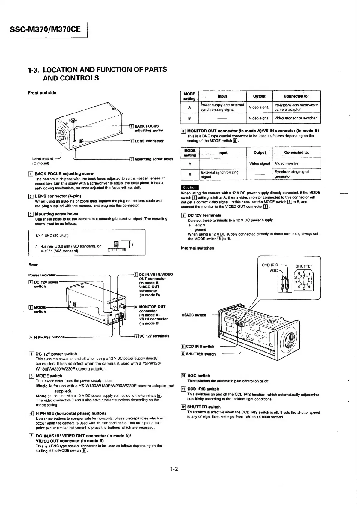
Front
and
side
MODE
setting
-
|
owt
|
output
|
Connecteato:
|
Power
supply
and
external
;
YS-W130/W130P/
W230/We30P
synchronizing
signal
Video
signal
camera
adaptor
fs
|
—
|
Video
signal
|
Video
monitor
or
switcher
[1]
BACK
FOCUS
adjusting
screw
MONITOR
OUT
connector
(in
mode
A)/VS
IN
connector
(in
mode
B)
This
is
a
BNC
type
coaxial
connector
to
be
used
as
follows
depending
on
the
[2]
LENS
connector
setting
of
the
MODE
switch
[5].
Lens
mount
{3]
Mounting
screw
holes
(C
mount)
{1}
BACK
FOCUS
adjusting
screw
External
synchronizing
Synchronizing
signal
The
camera
is
shipped
with
the
back
focus
adjusted
to
suit
almost
ail
lenses.
If
signal
generator
necessary,
turn
this
screw
with
a
screwdriver
to
adjust
the
focal
plane.
It
has
a
self-locking
mechanism,
so
once
adjusted
the
focus
will
not
drift.
When
using
the
camera
with
a
12
V
DC
power
supply
directly
conected,
if
the
MODE
22)
LENS
connector
(4-pin)
switch
[5]
setting
is
left
at
A,
then
a
video
monitor
connected
to
this
connector
wilt
When
using
an
auto-iris
or
zoom
lens,
replace
the
plug
on
the
lens
cable
with
not
get
a
correct
video
signal.
In
this
case,
set
the
MODE
switch
[S]to
B,
and
the
plug
supplied
with
the
camera,
and
plug
into
this
connector.
connect
the
monitor
to
the
VIDEO
OUT
connector
[7].
[3]
Mounting
screw
holes
[3]
De
12V
terminals
Use
these
holes
to
fix
the
camera
to
a
mounting
bracket
or
tripod.
The
mounting
Sonnect
these
terminals
to
a
12
V
DC
power
supply.
screw
must
be
as
follows.
Connect
these
termi
C
pl
pply.
+:
+12V
—:
ground
4/4ā€
UNC
(20
pitch)
When
using
a
12
V
DC
supply
connected
directly
to
these
terminals,
always
set
the
MODE
switch
[5
]to
8.
€:
4.5mm
+0.2
mm
(ISO
standard),
or
=
{
e
internal
enuchiea
0.197ā€
(ASA
standard)
Power
indicator.
DC
IN.VS
IN/VIDEO
OUT
connector
(in
mode
A)
VIDEO
OUT
connector
(in
mode
B)
{8]
MONITOR
OUT
connector
(in
mode
A)
[10]
AGC
switch
VS
IN
connector
(in
mode
B)
[6]
H
PHASE
buttons
[3]DC
12V
terminals
[ii]
CCD
IRIS
switch
[4]
DC
12V
power
switch
[12]
SHUTTER
switch
This
turns
the
power
on
and
off
when
using
a
12
V
DC
power
supply
directly
connected.
It
has
no
effect
when
the
camera
is
used
with
a
YS-W130/
W130P/W230/W230P
camera
adaptor.
=
[5]
MODE
switch
AGC
switch
This
switch
determines
the
power
supply
mode.
This
switches
the
automatic
gain
control
on
or
off.
Mode
A:
for
use
with
a
YS-W130/W130P/W230/W230P
camera
adaptor
(not
i
IRIS
switch
supplied).
CCD
IRIS
swite
Mode
B:
for
use
with
a
12
V
DC
power
supply
connected
to
the
terminals
[9].
This
switches
on
and
oft
the
ccD
IRIS
function,
which
automatically
adjuststine
The
video
connectors
7
and
8
also
have
different
functions
depending
on
the
Sensitivity
according
to
the
incident
light
conditions.
m
ting.
ileal
[2]
SHUTTER
switch
[6]
H
PHASE
(horizontal
phase)
buttons
This
Switch
is
effective
when
the
CCD
IRIS
switch
is
off.
It
sets
the
shutter
seed
Use
these
buttons
to
compensate
for
horizontal
phase
discrepancies
which
will
to
any
of
eight
fixed
settings,
from 1/60
to
1/10000
second.
occur
when
the
camera
is
used
with
an
extended
cable.
Use
the
tip
of
a
ball-
point
pen
or
similar
instrument
to
press
the
buttons,
which
are
recessed.
DC
IN.VS
IN/
VIDEO
OUT
connector
(in
mode
A)/
VIDEO
OUT
connector
(in
mode
B)
This
is
a
BNC
type
coaxial
connector
to
be
used
as
follows
depending
on
the
setting
of
the
MODE
switch
[5].
1-2