Do you have a question about the Sony ST-JX4L and is the answer not in the manual?
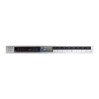
Details model number, frequency range, IF, and power specifications.
Guidance on using ceramic capacitors, their types, and identification.
Explains the color coding system for ceramic capacitors and resistors.
Steps for safely storing and handling MOS ICs during replacement to prevent static damage.
Methods to prevent potential differences when checking C-MOS ICs.
Steps for mounting ICs using clips or shorting wires to maintain equal potential.
Details input/output ports and functions of the controller IC503.
Illustrates the switching and display logic matrix for tuner operations.
Illustrates internal circuitry and signal flow via a block diagram.
Explains tuning and memorizing stations using preset buttons for simplified operation.
Instructions for removing the top cover and front panel.
Steps for safely removing the bottom plate to access internal components.
Procedures for AM IF alignment, tracking, and frequency coverage for MW/LW.
Covers FM discriminator, VCO, stereo separation, muting, and cal tone adjustments.
Shows physical placement and connection of components on circuit boards.
Illustrates pin configurations for various semiconductor components.
Details identification colors of FM ceramic filters for adjustment.
Illustrates disassembly and parts of the main unit chassis.
Shows assembly and parts of the tuner and preset boards.
Lists accessories, packing materials, and notes on parts.
| Tuning range (AM) | 530 - 1605 kHz |
|---|---|
| Total Harmonic Distortion (AM) | 0.5% |
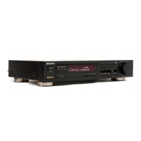
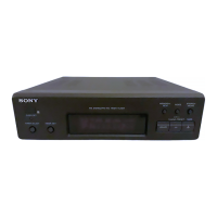
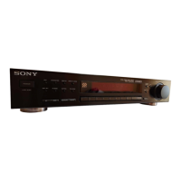
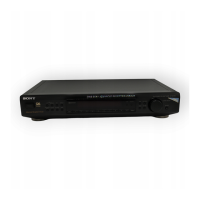
| Type | Tuner |
| Tuning range (FM) | 87.5 - 108.0 MHz |
| FM sensitivity | 1.9 µV (IHF) |
| Total Harmonic Distortion (FM) | 0.1% |
| Dimensions | 430 x 120 x 300 mm |
| Sensitivity (FM) | 1.9 µV (IHF) |