EasyManua.ls Logo

Sony ST-S3 Service Manual

Sony ST-S3
34 pages
To Next Page IconTo Next Page
Page #1 background imageLoading...
Page #1 background image
SERVICE MANUAL
FM STEREO, FM/AM
SUPERHETERODYNE TUNER
AEP Model
UK Model
SPECIFICATIONS
ST-S3
Ver 1.0 2001.05
ST-S3 is the tuner section
in MHC-S3.
Tuner section
FM stereo, FM/AM superheterodyne tuner
FM tuner section
Tuning range 87.5 – 108.0 MHz
Antenna FM lead antenna
Antenna terminals 75 ohm unbalanced
Intermediate frequency 10.7 MHz
AM tuner section
Tuning range 531 – 1,602 kHz
(with the interval set at
9 kHz)
Antenna AM loop antenna
Antenna terminals External antenna terminal
Intermediate frequency 450 kHz
Dimensions (w/h/d)
Approx. 280 x 108 x 340 mm
Mass
Approx. 2.1 kg
Design and specifications are subject to change
without notice.
9-873-873-11 Sony Corporation
2001E0500-1 Home Audio Company
C 2001.5 Shinagawa Tec Service Manual Production Group
Question and Answer IconNeed help?

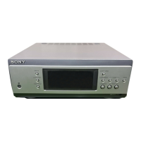
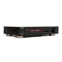
Do you have a question about the Sony ST-S3 and is the answer not in the manual?

Sony ST-S3 Specifications

General IconGeneral
Tuning BandsFM, MW
Intermediate Frequency (FM)10.7 MHz
Tuning ScaleAnalogue
FM Tuning Range87.5 - 108 MHz
Frequency Response (FM)30 - 15, 000 Hz

Summary

ST-S3 Specifications

FM Tuner Section Specifications

Technical details for the FM tuner, including tuning range and antenna type.

AM Tuner Section Specifications

Technical details for the AM tuner, including tuning range and antenna type.

ST-S3 Servicing Notes and General Information

Servicing Notes

Important servicing precautions and system configuration notes.

General Unit Information and Controls

Location of controls and instructions for setting the unit's time.

ST-S3 Remote Control Operations

Setting the Time Using the Remote Control

Step-by-step guide for setting the unit's clock using the remote.

Remote Control Button Descriptions

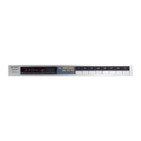
Explanation of each button's function on the remote control.

ST-S3 Disassembly Procedures

Disassembly Flow and Component Removal Steps

Sequential guide for disassembling the unit, including cover and board removal.

ST-S3 Test Mode Operations

Test Mode Entry, Management, and Exit

Procedures for entering, operating, and releasing diagnostic test modes.

ST-S3 Diagrams and Schematics

Notes on Diagram and Schematic Interpretation

Guidelines for understanding symbols, notations, and circuit board layout.

Schematic Diagrams for Main, DSP, and Panel Boards

Detailed circuit schematics for the main, DSP, and panel boards.

ST-S3 Integrated Circuit (IC) Pin Function Descriptions

Main Board IC501 Pinout Description

Detailed pin assignments and functions for the main system controller IC.

DSP and Panel IC Pinout Descriptions

Pinout details for DSP board ICs (CXD9617R, LC89056W-E, AK4527) and Panel IC.

ST-S3 Exploded Views

Assembly Views of External and Internal Parts

Visual breakdown of the unit's cover, front panel, and chassis components.

ST-S3 Electrical Parts List

Capacitors and Resistors

Lists of capacitors and resistors with part numbers and specifications.

Component Lists for Maintenance

Lists for ICs, connectors, diodes, transistors, switches, and other parts.

ST-S3 Revision History

Revision History Log

Records of changes and updates made to the service manual.

Related product manuals