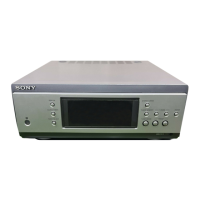
ST-S3
2020
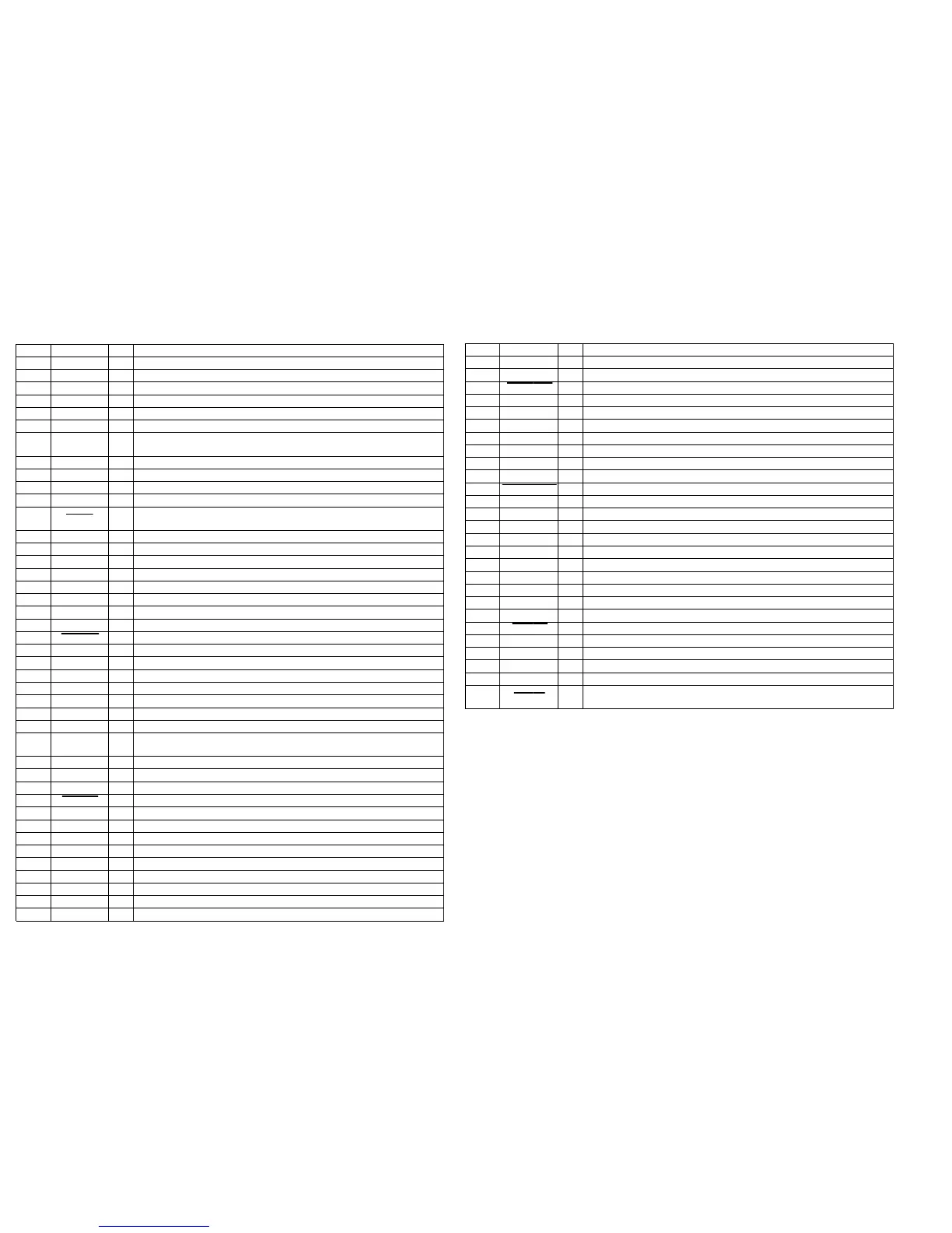
5-10. IC PIN FUNCTION DESCRIPTION
• MAIN BOARD IC501 M30622MGA-A39FP (SYSTEM CONTROLLER)
Pin No. Pin Name I/O Description
1 AMP-DATA O
Serial data output to the M61512FP (IC607)
2 AMP-CLK O
Serial data transfer clock signal output to the M61512FP (IC607)
3 AMP-LAT O
Serial data latch pulse signal output to the M61512FP (IC607)
4 SIRCS I
Remote control signal input from the remote control receiver (IC101)
5 DIG-TX O
Serial data output to the CXD9617R (IC601), digital audio interface receiver (IC604)
6 DSP-RX
I Serial data input from the digital audio interface receiver (IC604)
7 DIG-CLK
O
Serial data transfer clock signal output to the CXD9617R (IC601), digital audio interface receiver
(IC604)
8 GND —
Ground terminal
9 CNVSS —
Not used
10 XCIN I
Sub system clock input terminal (32.768 kHz)
11 XCOUT O
Sub system clock output terminal (32.768 kHz)
12 RESET I
System reset signal input from the reset signal generator (IC551) “L”: reset
For several hundreds msec. after the power supply rises, “L” is input, then it changes to “H”
13 XOUT O
Main system clock output terminal (16 MHz)
14 VSS —
Ground terminal
15 XIN I
Main system clock input terminal (16 MHz)
16 VCC —
Power supply terminal (+5V)
17 NMI I
Non-maskable interrupt input terminal Fixed at “H” in this set
18 RDS-INT
I Serial data transfer clock signal from the RDS decoder on the FM/AM tuner unit
19 ——
Not used (open)
20 RDS-DATA
I Serial data input from the RDS decoder on the FM/AM tuner unit
21 ST-MUTE O
Tuner muting on/off control signal output to the FM/AM tuner unit “L”: muting on
22 ST-CE O
Chip enable signal output to the FM/AM tuner unit
23 ST-DOUT O
Serial data output to the FM/AM tuner unit
24 ——
Not used (open)
25 ST-DIN
I Serial data input from the FM/AM tuner unit
26 ——
Not used (open)
27 ST-CLK
O Serial data transfer clock signal output to the FM/AM tuner unit
28 ——
Not used (open)
29 IIC CLK I/O
Communication data reading clock signal input or transfer clock signal output with the display
controller (IC601) and CDP-S3
30 IIC DATA I/O
Communication data bus with the display controller (IC601) and CDP-S3
31 to 34 NO-USE —
Not used
35 to 40 ——
Not used (open)
41 M-RESET O
Reset signal output to the display controller (IC601) “L”: reset
42 to 50 ——
Not used (open)
51 NO-USE —
Not used
52 to 57 ——
Not used (open)
58 EXP-IN DATA
I Serial data input from the I/O expander in the TA-S3
59 EXP-OUT DATA O
Serial data output to the I/O expander in the TA-S3
60 EXP-LAT O
Serial data latch pulse signal output to the I/O expander in the TA-S3
61 EXP-CLK O
Serial data transfer clock signal output to the I/O expander in the TA-S3
62 VCC —
Power supply terminal (+5V)
63 SOFT-TEST
I Soft test output terminal Not used (open)
Pin No. Pin Name I/O Description
64
VSS — Ground terminal
65 to 70 ——
Not used (open)
71 LINE-MUTE
O Audio line muting on/off control signal output to the audio line circuit “L”: muting on
72 ——
Not used (open)
73 DISPLAY KEY I
DISPLAY switch (S601) input terminal
74 POWER KEY I
Power on/off switch in the TA-S3 input terminal
75 DIR-UNLOCK
I PLL lock error and data error flag input from the digital audio interface receiver (IC604)
76 DIR-CS O
Chip enable signal output to the digital audio interface receiver (IC604)
77 DIR-XSTATE
I Source clock switching monitor input from the digital audio interface receiver (IC604)
78 DIR-RX
I Read data input from the digital audio interface receiver (IC604)
79 CODEC-SMUTE O
Soft muting on/off control signal output to the A/D, D/A converter (IC605) “L”: muting on
80 DSP-ACK
I Acknowledge signal input from the CXD9617R (IC601)
81 DSP-CS
O Chip select signal output to the CXD9617R (IC601)
82 DSP-DECODE
O Decode signal input from the CXD9617R (IC601)
83 to 86 ——
Not used (open)
87 STEREO I
FM stereo detection signal input from the FM/AM tuner unit “L”: stereo
88 TUNED I
Tuning detection signal input from the FM/AM tuner unit “L”: tuned
89 to 91 ——
Not used (open)
92 MODEL-IN
I Model setting terminal
93
SPEC-IN I Specification setting terminal
94 ——
Not used (open)
95 V-MUTE O
Video muting on/off control signal output terminal “L”: muting on Not used (open)
96
AVSS — Ground terminal
97 ——
Not used (open)
98
VREF
I
Reference voltage (+5V) input terminal
99 AVCC —
Power supply terminal (+5V)
100 AC-CUT I
AC cut on/off detection signal input from the reset signal generator (IC551)
“L”: AC cut on, “H”: AC cut off or checked