Tuner
section
FM
tuner
section
AM
tuner
section
Tuning
range
|
87.5
-
108
MHz
530
-
1710
kHz
(10
kHz
step)
531
-
1602
kHz
(9
KHz
step)
1
300
ohms,
balanced
External
antenna
75
ohms,
unbalanced
terminal
Sensitivity
at
|
18.3
dB,
4.5
nV
(mono)
50
dB
quieting!
38.3
dBf,
45
wV
(stereo)
—
(US
and
Canadian
models)
and
46
dB
(UK,
E,
Australian
model)
terminals
11.2
dBi,
2
pV
(IHF)
Loop
antenna:
sensitivity
500
pV
(at
1,000
kHz)
76
dB
(mono)
54
dB
(at
50
mV/m)
Signal-to-noise
ratio
70
dB
(stereo)
Harmonic
0.3%
(mono),
0.5%
0.5%
(at
50
mV/m,
distortion
(stereo)
at
1
KHz
400
Hz)
Selectivity
60
dB
at
400 kHz
40
dB
at
10
kHz
Separation
45
dB
at
1
kHz
Frequency
30
Hz
—
15
kHz
response
12°
dB
General
System
Tuner
section:
PLL
quartz-locked
digital
synthesizer
system
Preamplifier
section:
low-noise
NF
type
equalizer
amp
Power
amplifier
section:
pure
complementary
SEPP
Power
requirements
US,
Canadian
model
:
120V
AC,
60Hz
UK,
Australian
model
:
240V
AC,
50Hz
E
model
:
120V,
220V
or
240V
AC,
adjustable
50/60Hz
Power
consumption
US
model:
135
W
Canadian
model:
150
W
UK,
E,
Australian
model:
125
W
In
standby
condition:
5
W
AC
outlet
US
and
Canadian
models
:
One
switched
(120W/1A
Max.)
Australian
mode!:
100
W
switched
E
model
:
One
switched
(100
W
Max.)
Dimensions
Approx.
430
x
135
x
295
mm
(w/h/d)
(17x
5%,
x
11°,
inches)
including
projecting
parts
and
controls
Weight
Approx.
6.2
kg
(13
Ib
1
0z)
Accessories
supplied
FM
wire
antenna
(1)
AM
loop
antenna
(1)
Remote
commander
RM-S103
(1)
Sony
batteries
SUM-3(NS)
(2)
Design
and
specifications
are
subject
to
change
without
notice.
SAFETY-RELATED
COMPONENT
WARNING!!
COMPONENTS
IDENTIFIED
BY
MARK
A
OR
DOTTED
LINE
WITH
MARK
A
ON
THE
SCHEMATIC
DIAGRAMS
AND
IN
THE
PARTS
LIST
ARE
CRITICAL
TO
SAFE
OPERATION.
REPLACE
THESE
COMPONENTS
WITH
SONY
PARTS
WHOSE
PART
NUMBERS
APPEAR
AS
SHOWN
IN
THIS
MANUAL
OR
IN
SUPPLEMENTS
PUB-
LISHED
BY
SONY.
TABLE
OF
CONTENTS
ection
Title
Page
SECTION
1.
GENERAL
Identifying
the
Parts
and
Controls
.......c.cccceessssececeeceteeeesesenecesseeeeeceeeerseeenes
3
SECTION
2.
DIAGRAMS
2-1.
Circuit
Boards
Location...
ccccssccsseesececeeceeeseeeeseceaecnaneaeearees
5
2-2.
Semiconductor
Lead
Layouts
.0..........cccceeeececeeeneeereteteeecntenaeeenes
5
2-3;
Block
Digeran:::...
asic
sicavina
orcad
hha
cians
tieete
sateen
6
2-4.
Printed
Wiring
Board
—
Main
Section
—
..0...0.cc
eect
9
2-5.
Schematic
Diagram
—
Main
Section
—
.......ccceeseeetseeeesereenees
13
2-6.
Printed
Wiring
Board
—
Display
Section
—
..0...
ieee
18
2-7.
Schematic
Diagram
—
Display
Section
—
.........
ce
eeseeseeererees
20
2-8.
IC
Block
Diagrams
o.0......
ee
eceseeseseeeeentseeeeneeeeeeeeeeeeaeseersnesseeases
23
SECTION
3.
EXPLODED
VIEWS
3-1.
Front
Panel
Section
0.0...
ccccccccccsccsceecereceeeesessenes
phd
et
ae
he
24
B22).
CHASSIS:
SOCHON
cociccscscsiaessexesssatensceiccstvavecseadeenes
vwiseesdecavascissaksiesetie
25
SECTION
4.
ELECTRICAL
PARTS
LIST
......................5
26
MODEL
IDENTIFICATION
—
Model
Number
Label—
SON
Ye
mover
no.stR-p311
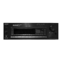
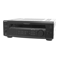
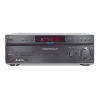
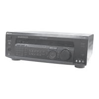
FM
STEREO/FM-AM
RECEIVER
WML
LLL
US,
Canadian
model
:
AC
120V,
60Hz,
135W
(US),
150W
(CND)
UK,
Australian
model
:
AC
240V,
50Hz
E
model
AC
120V,
220/240V,
50/60Hz,
125W
ATTENTION
AU
COMPOSANT
AYANT
RAPPORT
A
LA
SECURITE!
LES
COMPOSANTS
IDENTIFIES
PAR
UNE
MARQUE
/\
SUR
LES
DIAGRAMMES
SCHEMATIQUES
ET
LA
LISTE
DES
PIECES
SONT
CRITIQUES
POUR
LA
SECURITE
DE
FONCTIONNEMENT.
NE
REMPLACER
CES
COM-
POSANTS
QUE
PAR
DES
PIECES
SONY
DONT
LES
NUMEROS
SONT
DONNES
DANS
CE
MANUEL
OU
DANS
LES
SUPPLEMENTS
PUBLIES
PAR
SONY.
 Loading...