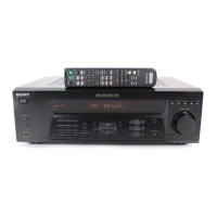
Do you have a question about the Sony STR-D565 and is the answer not in the manual?
Details power output for Stereo and Surround modes across different models.
Details tuning range, antenna terminals, sensitivity, and S/N.
Covers frequency response, sensitivity, input impedance, and output details.
Explains the 'PROTECT' display and how to cancel it.
Instructions for preventing the 'PROTECT' mode by short-circuiting.
Diagram showing the location of test points on the main board.
Step-by-step guide for operating the FL check mode.
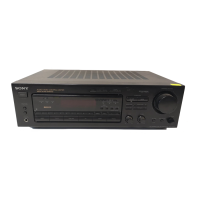
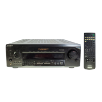
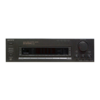
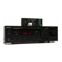
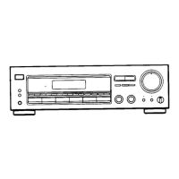
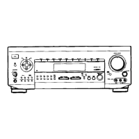
Identifies and describes front panel buttons, indicators, and displays.
Illustrates and lists rear panel input/output terminals and connectors.
Procedure for disassembling the unit's outer case and front panel.
Steps to remove the display and tone circuit boards.
Instructions for removing the unit's back panel.
Steps for removing the SP SW circuit board.
Procedure for removing the main circuit board.
Steps for disassembling specific control boards.
Diagram showing the placement of all main circuit boards.
Detailed layout of the main circuit board's wiring.
Circuit schematic for the main section of the unit.
Detailed layout of the display circuit board's wiring.
Circuit schematic for the display section of the unit.
Block diagrams for various integrated circuits used in the unit.
Detailed pin assignments and functions for IC201.
Continuation of pin functions for IC201.
Exploded diagram of the unit's case and front panel parts.
Exploded diagram of the unit's internal chassis and components.
Exploded diagram of the main internal section and its parts.
List of electrical parts for AC SW and Display sections.
List of electrical parts for the Display section.
List of electrical parts for Display and Main sections.
List of electrical parts for the Main section.
Further list of electrical parts for the Main section.
Additional electrical parts for the Main section.
Final list of electrical parts for the Main section.
List of electrical parts for the Main section.
More parts for the Main section.
Additional parts for the Main section.
Final parts for the Main section.
Parts list for Primary SP SW, Jack, and Resistor sections.
Parts list for various boards and components.
Parts list for Tone, Trans, V-Select, and Video sections.
Parts list for Video-Main and Vol boards.
Parts for Vol-Main board, connectors, and miscellaneous items.
Details corrections to the main service manual.
Information regarding updated or changed circuit boards.
Highlights corrections to the main section's printed wiring board.
Details corrections for the main section's schematic diagram.
Highlights corrections on the display board diagram.
Compares former and new versions of the main board's wiring.
| Brand | Sony |
|---|---|
| Model | STR-D565 |
| Category | Stereo Receiver |
| Language | English |