EasyManua.ls Logo

Sony STR-K870P User Manual

Sony STR-K870P
58 pages
To Next Page IconTo Next Page
Page #1 background imageLoading...
Page #1 background image
SERVICE MANUAL
Sony Corporation
Audio Group
Published by Sony Engineering Corporation
US Model
Canadian Model
AEP Model
UK Model
E Model
Australian Model
FM STEREO FM-AM RECEIVER
9-879-448-01
2005B1678-1
© 2005.02
Ver. 1.0 2005.02
SPECIFICATIONS
STR-K870P
STR-K870P is the tuner and the amplifier
section in HT-DDW870.
Manufactured under license from Dolby Laboratories.
“Dolby”, “Pro Logic” and the double-D symbol are trademarks of
Dolby Laboratories.
“DTS” and “DTS Digital Surround” are registered trademarks of
Digital Theater Systems, Inc.
Models of area code AUS
(6 ohms 120 Hz – 20 kHz, THD 0.09%)
FRONT
2)
: 50 W/ch
CENTER
2)
: 50 W
SURR
2)
: 50 W/ch
SURR BACK
2)
: 50 W
(6 ohms 1 kHz, THD 0.7%)
FRONT
2)
: 60 W/ch
CENTER
2)
: 60 W
SURR
2)
: 60 W/ch
SURR BACK
2)
: 60 W
(6 ohms 1 kHz, THD 10%)
FRONT
2)
: 100 W/ch
CENTER
2)
: 100 W
SURR
2)
: 100 W/ch
SURR BACK
2)
: 100 W
AUDIO POWER SPECIFICATIONS
POWER OUTPUT AND TOTAL HARMONIC
DISTORTION:
(Models of area code US only)
With 6 ohm loads, both channels driven, from
120 – 20,000 Hz; rated 60 watts per channel
minimum RMS power, with no more than 0.7%
total harmonic distortion from 250 milliwatts to
rated output.
Amplifier section
Power Output
1)
Models of area code US, CND
(6 ohms 1 kHz, THD 0.7%)
FRONT
2)
: 60 W/ch
CENTER
2)
: 60 W
SURR
2)
: 60 W/ch
SURR BACK
2)
: 60 W
(6 ohms 1 kHz, THD 10%)
FRONT
2)
: 100 W/ch
CENTER
2)
: 100 W
SURR
2)
: 100 W/ch
SURR BACK
2)
: 100 W
Models of area code AEP, UK, SP, E51, MX
(6 ohms 1 kHz, THD 0.7%)
FRONT
2)
: 60 W/ch
CENTER
2)
: 60 W
SURR
2)
: 60 W/ch
SURR BACK
2)
: 60 W
(6 ohms 1 kHz, THD 10%)
FRONT
2)
: 100 W/ch
CENTER
2)
: 100 W
SURR
2)
: 100 W/ch
SURR BACK
2)
: 100 W
– Continued on next page –
Question and Answer IconNeed help?

Do you have a question about the Sony STR-K870P and is the answer not in the manual?

Sony STR-K870P Specifications

General IconGeneral
Impedance8 ohms
Number of Channels5.1
Tuning rangeAM/FM
Total Harmonic Distortion0.09%
Input sensitivity450 mV
Speaker Impedance8 ohms
Inputs1 x digital audio input (coaxial), 1 x digital audio input (optical)
Outputsheadphones
Speaker load impedance8 ohms
Video ConnectionsComposite

Summary

SERVICE MANUAL

STR-K870P Product Overview

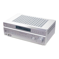
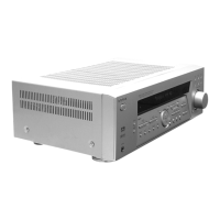
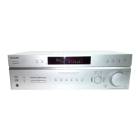
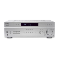
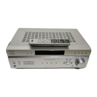
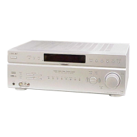
Identifies the STR-K870P receiver and its variants.

Specifications Overview

Details audio power and amplifier section specifications.

Specifications Details

Video, General, and Tuner Specifications

Details video, general, FM, and AM tuner specifications.

Safety and Component Handling

AC Leakage Test and Component Notes

AC leakage test procedure, chip component, and solder handling notes.

Model Identification and Parts

Model Identification and Part Numbers

Back panel model identification and model-specific part numbers.

General Unit Information

Main Unit Layout and Controls

Diagram of the main unit with labeled controls and jacks.

Remote Control Usage

Remote Control Installation and Operation

Instructions for battery installation, tips, notes, and button identification.

Remote Control Button Functions (Part 1)

Remote Functions A.F.D. to AV I/O

Describes functions for A.F.D., ALT, ANT, AUDIO, AUX, AV MENU, AV1/AV2, AV I/O.

Remote Control Button Functions (Part 2)

Remote Functions MASTER VOL to SHIFT

Describes functions for MASTER VOL, MD/TAPE, MOVIE, MULTI CH, MUSIC, MUTING, PRESET/CH, D.SKIP, RETURN/EXIT, RM SET UP, SA-CD/CD, SB DECODING, SEARCH MODE, SHIFT.

Remote Control Button Functions (Part 3)

Remote Functions Numeric Keys and Navigation

Describes functions for numeric keys, channel entry, and power controls.

Remote Control Modes and Settings

Remote Command Mode Management

Procedures for checking, changing, and resetting remote command modes.

Test Modes

Test Modes: Presets and System Configuration

Covers FACTORY PRESET, AM CHANNEL STEP, SOUND FIELD CLEAR, CHANGE COMMON, SHIPMENT modes.

Test Modes: Display and Operational Checks

Covers FLUORESCENT INDICATOR, SOFTWARE VERSION DISPLAY, KEY CHECK modes.

Diagrams and Board Locations

Circuit Board Layout Diagram

Diagram showing the location of various circuit boards.

Schematic and PWB Conventions

Diagram Conventions and Waveform Examples

Notes on schematic/PWB symbols and waveform examples for DIGITAL Board.

Block Diagram: Main Section

Main Section Signal Path Indicators

Indicates the signal path for FM, ANALOG, DIGITAL, and VIDEO.

Block Diagram: Display/Power Section

Display/Power Section Signal Path Indicators

Indicates the signal path for FM, ANALOG, DIGITAL, and VIDEO.

Printed Wiring Board: Digital Board (Side A)

Digital Board (Side A) Semiconductor Locations

Table listing semiconductor locations on the DIGITAL BOARD (Side A).

Printed Wiring Board: Digital Board (Side B)

Digital Board (Side B) Semiconductor Locations

Table listing semiconductor locations on the DIGITAL BOARD (Side B).

Schematic Diagram: Digital Board (1/4)

Digital Board Schematic References

References to waveform and IC block diagram details for Digital Board (1/4).

Printed Wiring Board: Main Board

Main Board Semiconductor Locations

Table listing semiconductor locations on the MAIN BOARD.

Digital Board IC Block Diagrams

IC1131 and IC1301 Block Diagrams

Block diagrams for IC1131 BR24L16F-WE2 and IC1301 LC89056W-E.

IC Pin Function Descriptions

IC1101 (SYSTEM CONTROL) Pin Functions

Pin function description for IC1101 (SYSTEM CONTROL).

Exploded Views: Front Cabinet Section

Front Cabinet Section Parts List and Notes

Exploded view, parts list, and notes for the front cabinet section.

Exploded Views: Chassis Section-1

Chassis Section-1 Parts List

Exploded view and parts list for chassis section 1.

Electrical Parts List: Overview

Parts List Notes and AC Select Board

Notes on parts list and electrical parts for AC SELECT BOARD (E51).

Electrical Parts List: Digital Components

Digital Components Parts List

Electrical parts list for DIGITAL components.

Electrical Parts List: Display, Headphone, Main Components

Display, Headphone, Main Parts List

Electrical parts list for DISPLAY, HEADPHONE, and MAIN sections.

Electrical Parts List: Standby, Tuning, Video Components

Standby, Tuning, Video Parts List

Electrical parts list for STANDBY, TUNING, and VIDEO sections.

Related product manuals