EasyManua.ls Logo

Sony STR-KS600PW User Manual

Sony STR-KS600PW
54 pages
To Next Page IconTo Next Page
Page #1 background imageLoading...
Page #1 background image
SERVICE MANUAL
Amplifier section
Power Output
1)
Models of area code CEL, CEK
(4 ohms 1 kHz, THD 0.7%)
FRONT
2)
: 70 W/ch
CENTER
2)
: 70 W
SURR
2)
: 70 W/ch
(4 ohms 100 Hz, THD 0.7%)
SUB WOOFER
2)
: 70 W
(4 ohms 1 kHz, THD 10%)
FRONT
2)
: 100 W/ch
CENTER
2)
: 100 W
SURR
2)
: 100 W/ch
(4 ohms 100 Hz, THD 10%)
SUB WOOFER
2)
: 100 W
1) Measured under the following conditions:
2) Depending on the sound field settings and the
source, there may be no sound output.
Inputs (Analog)
Inputs (Digital)
Reproduction frequency range:
28 – 20,000 Hz
Tone
FM tuner section
Tuning range 87.5 - 108.0 MHz
Antenna FM wire antenna
Antenna terminals 75 ohms, unbalanced
Intermediate Frequency 10.7 MHz
AM tuner section
Tuning range
Models of area code CEL, CEK
With 9-kHz tuning scale: 531 - 1,602 kHz
Antenna Loop antenna
Intermediate Frequency 450 kHz
General
Power requirements
Power consumption
Power consumption (during standby mode)
0.3 W
Dimensions (w/h/d) (Approx.)
430 × 64 × 337 mm
including projecting parts
and controls
Mass (Approx.) 3.3 kg
Area code Power requirements
CEL, CEK 230 V AC, 50 Hz
SA-CD/CD, VIDEO 1, 2 Sensitivity: 1 V
Impedance: 50 kiloohms
DVD (Coaxial) Sensitivity: –
Impedance: 75 ohms
VIDEO 2, SA-CD/CD
(Optical)
Sensitivity:
Impedance: –
Gain levels ±6 dB, 1 dB step
Area code Power requirements
CEL, CEK 230 V AC, 50/60 Hz
Area code Power consumption
CEL, CEK 110 W
Design and specifications are subject to change
without notice.
FM STEREO/FM-AM RECEIVER
AEP Model
STR-KS600PM/KS600PW
UK Model
STR-KS600PM
SPECIFICATIONS
STR-KS600PM/KS600PW
STR-KS600PM is the receiver section in HT-SF800M.
STR-KS600PW is the receiver section in HTP-32SS.
Ver. 1.1 2006.03
9-879-722-02
2006C05-1
© 2006.03
Sony Corporation
Home Audio Division
Published by Sony Techno Create Corporation
This receiver incorporates Dolby* Digital and Pro
Logic Surround and the DTS** Digital Surround
System.
* Manufactured under license from Dolby
Laboratories.
“Dolby”, “Pro Logic” and the double-D symbol are
trademarks of Dolby Laboratories.
**“DTS” and “DTS Digital Surround” are registered
trademarks of Digital Theater Systems, Inc.
– Continued on next page –
Question and Answer IconNeed help?

Do you have a question about the Sony STR-KS600PW and is the answer not in the manual?

Sony STR-KS600PW Specifications

General IconGeneral
Number of Channels5.1
HDMI Outputs1
Audio DecodingDolby Digital, DTS
TunerAM/FM
Total Harmonic Distortion0.09%
Output Power100 Watts per channel (6 Ohms, 1 kHz, 1 channel driven)

Summary

Specifications

Amplifier Section

Power output details for various impedance and distortion levels.

Inputs (Digital)

Sensitivity and impedance for digital audio inputs.

Inputs (Analog)

Sensitivity and impedance for analog audio inputs.

Reproduction Frequency Range

Specifies the audio frequency response limits.

Tone Control

Details the range for bass and treble adjustments.

FM Tuner Section

Parameters for FM reception, including tuning and antenna.

AM Tuner Section

Parameters for AM reception, including tuning and antenna.

General Specifications

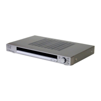
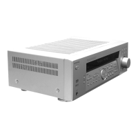
Unit dimensions, power consumption, and weight.

Servicing Notes

Unleaded Solder Handling

Information on characteristics and proper use of lead-free solder.

Digital Board Replacement Notes

Specific instructions for replacing the digital board components.

General Information

Location of Controls

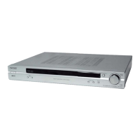
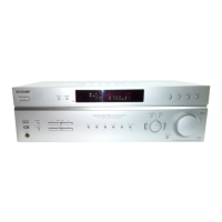
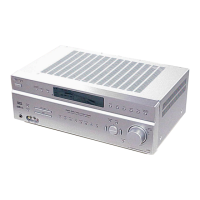
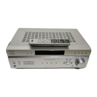
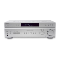
Identification of all buttons and indicators on the main unit.

Display Indicators Overview

Explanation of the meaning of illuminated indicators on the front panel display.

Remote Control Button Functions

Detailed description of operations controlled by the remote handset.

Disassembly Procedures

Disassembly Flow

Sequential steps for taking the unit apart.

Case Disassembly

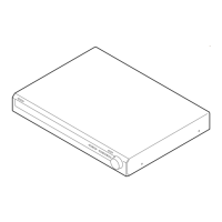
Instructions for removing the external enclosure.

Front Panel Assembly Removal

Procedure for detaching the front panel unit.

SMPS Board Removal

Steps to remove the Switched-Mode Power Supply board.

Line Filter Board Removal

Procedure for removing the line filter board.

D-AMP Board Removal

Steps to remove the Digital Amplifier board.

Digital Board Removal

Procedure for removing the main digital processing board.

Test Modes

Factory Preset Mode

Resets all settings to factory defaults.

All Clear Mode

Clears all user-configured memory.

FL Check Mode

Tests all front panel display segments and LEDs.

Version Mode

Displays model, region, and software version.

Key Check Mode

Verifies the operation of all front panel buttons.

Protector Auto Off Mode

Manages protection circuit status.

Sound Field Clear Mode

Resets all sound field settings.

RDS Autobetical Mode

Automatic scanning and storage of RDS radio stations.

Diagrams and Schematics

Block Diagram - DSP Section

Illustrates the Digital Signal Processor signal flow.

Block Diagram – Audio Out Section

Shows the audio signal path to the amplifiers.

Block Diagram - Display, Power Supply Section

Depicts power supply and display control signal paths.

Circuit Boards Location

Diagram indicating the physical placement of circuit boards.

Printed Wiring Board - Digital Board (Component Side)

Layout of components on the digital board.

Schematic Diagram - Digital Board (1/3)

Part one of the digital board's circuit schematic.

Schematic Diagram - Digital Board (2/3)

Part two of the digital board's circuit schematic.

Schematic Diagram - Digital Board (3/3)

Part three of the digital board's circuit schematic.

Printed Wiring Board - D-AMP Board (Component Side)

Component layout for the D-AMP board.

Printed Wiring Board - D-AMP Board (Conductor Side)

Tracks layout for the D-AMP board.

Schematic Diagram - D-AMP Board (1/2)

Part one of the D-AMP board's circuit schematic.

Schematic Diagram - D-AMP Board (2/2)

Part two of the D-AMP board's circuit schematic.

Printed Wiring Boards - Display Section

Component and track layout for the display board.

Schematic Diagram - Display Section

Circuit schematic for the display section.

Schematic Diagram - Speaker Out, Power Supply Section

Circuit schematic for PSU/speaker output.

IC Block Diagrams

Internal functional diagrams of key integrated circuits.

IC Pin Function Description

Detailed pinout and function list for integrated circuits.

Exploded Views

Cover Section Exploded View

Diagram of parts making up the unit's cover.

Chassis Block Exploded View

Diagram of the main structural chassis components.

Electrical Parts List

Related product manuals