Do you have a question about the Sony STR-KS600PM and is the answer not in the manual?
Details power output specifications for different impedance and distortion levels.
Covers power requirements, consumption, dimensions, and mass of the receiver.
Illustrates the signal flow and components within the Digital Signal Processor section.
Shows the signal path and components involved in audio output processing.
Depicts the interconnections between the display, power supply, and control units.
Provides the first part of the digital board's circuit schematic.
Presents the second part of the digital board's circuit schematic.
Offers the final part of the digital board's circuit schematic.
Displays the first half of the Digital Amplifier board's circuit schematic.
Provides the second half of the Digital Amplifier board's circuit schematic.
Details the circuit schematic for the display section, including volume control.
Circuit schematic for speaker output and power supply sections.
| Number of channels | 5.1 |
|---|---|
| HDMI outputs | 1 |
| Component video outputs | 1 |
| Composite video inputs | 2 |
| Composite video outputs | 1 |
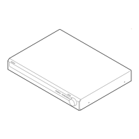
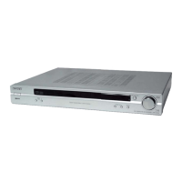
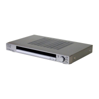
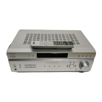
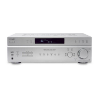
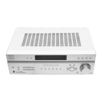
| Type | AV Receiver |
| Audio outputs | 1 x Headphone |
| Tuner | FM/AM |
| Inputs | HDMI, Component, Composite, Audio |
| Outputs | HDMI, Component, Composite, Audio |