EasyManua.ls Logo

Sony STR-K9900P User Manual

Sony STR-K9900P
58 pages
To Next Page IconTo Next Page
Page #1 background imageLoading...
Page #1 background image
1
SERVICE MANUAL
US Model
STR-K5900P/K9900P
Canadian Model
STR-K5900P
STR-K5900P/K9900P
FM STEREO/FM-AM RECEIVER
AUDIO POWER SPECIFICATIONS
POWER OUTPUT AND TOTAL HARMONIC
DISTORTION:
(Models of area code US only)
With 6 ohm loads, both channels driven, from
120 – 20,000 Hz; rated 90 watts (STR-K9900P)/
70 watts (STR-K5900P) per channel minimum
RMS power, with no more than 0.7 % total
harmonic distortion from 250 milliwatts to rated
output.
Amplifier section
Power Output
1)
Model of area code US
(6 ohms 1 kHz, THD 10 %)
STR-K9900P: FRONT
2)
: 140 W/ch
CENTER
2)
: 140 W
SURR
2)
: 140 W/ch
SURR BACK
2)
: 140 W
STR-K5900P: FRONT
2)
: 110 W/ch
CENTER
2)
: 110 W
SURR
2)
: 110 W/ch
SURR BACK
2)
: 110 W
SPECIFICATIONS
Model of area code Canadian
(6 ohms 1 kHz, THD 0.7 %)
STR-K5900P: FRONT
2)
: 70 W/ch
CENTER
2)
: 70 W
SURR
2)
: 70 W/ch
SURR BACK
2)
: 70 W
(6 ohms 1 kHz, THD 10 %)
STR-K5900P: FRONT
2)
: 110 W/ch
CENTER
2)
: 110 W
SURR
2)
: 110 W/ch
SURR BACK
2)
: 110 W
1) Measured under the following conditions:
Area code Power requirements
US, Canadian 120 V AC, 60 Hz
2) Depending on the sound field settings and the
source, there may be no sound output.
Ver. 1.0 2005. 03
9-879-562-01
2005C04-1
© 2005. 03
Sony Corporation
Audio Group
Published by Sony Engineering Corporation
Manufactured under license from Dolby Laboratories.
“Dolby”, “Pro Logic” and the double-D symbol are
trademarks of Dolby Laboratories.
“DTS”, “DTS-ES”, “Neo:6” and “DTS 96/24” are
trademarks of Digital Theater Systems, Inc.
– Continued on next page –
Photo: STR-K9900P
STR-K5900P/K9900P are the
FM/AM receiver section in
HT-5950DP/6900DP/9900M.
Question and Answer IconNeed help?

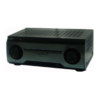
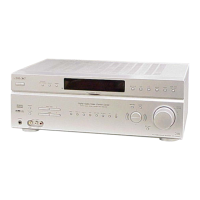
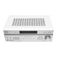
Do you have a question about the Sony STR-K9900P and is the answer not in the manual?

Sony STR-K9900P Specifications

General IconGeneral
Tuning rangeFM, AM
Surround Sound FormatsDolby Digital, DTS
Video InputsComposite
Video OutputsComposite
Digital inputsOptical, Coaxial

Summary

Disassembly Procedures

Digital Board Removal

Procedure for removing the digital board, showing screws and connectors.

Standby Board Removal

Procedure for removing the standby board, detailing screws and connectors.

Main Board Removal

Instructions for removing the main board, including screws and connectors.

Test Modes

Diagrams and Schematics

Block Diagram - Tuner/Audio Section

Shows signal flow and component relationships in the tuner and audio processing sections.

Block Diagram - Power Section

Illustrates the power supply system, including transformers, regulators, and protection circuits.

Schematic Diagram - Main Section (1/2)

Detailed schematic of the main board, covering audio and control circuits.

Schematic Diagram - Main Section (2/2)

Continuation of the main board schematic, focusing on power amplifier driver stages.

Schematic Diagram - Digital Section (1/4)

Part 1 of the digital section schematic, showing audio interface receiver and DACs.

Schematic Diagram - Digital Section (2/4)

Part 2 of the digital section schematic, detailing SDRAM and DSP connections.

Schematic Diagram - Digital Section (3/4)

Part 3 of the digital section schematic, showing ADCs and amplifier circuits.

Schematic Diagram - Digital Section (4/4)

Part 4 of the digital section schematic, showing system control and power regulators.

Schematic Diagram - Power Section

Schematics for power transformers, regulators, and standby power circuits.

Electrical Parts List

Related product manuals