Do you have a question about the Sony TA-FE530R and is the answer not in the manual?
| Frequency Response | 7 Hz - 100 kHz |
|---|---|
| Total Harmonic Distortion (THD) | 0.008% |
| Dimensions | 430 x 150 x 310 mm |
| Damping factor | 100 |
| Input sensitivity | 2.5 mV (MM), 150 mV (line) |
| Total harmonic distortion | 0.008% |
| Type | Stereo Integrated Amplifier |
| Inputs | Phono, CD, Tuner, Tape 1, Tape 2 |
| Outputs | Tape 1, Tape 2 |
| Signal to noise ratio | 80 dB (MM), 103 dB (line) |
| Output | 2 (Speaker A, Speaker B) |
| Speaker load impedance | 4 Ohm to 16 Ohm |
Details on the amplifier's power output, frequency response, S/N ratio, and impedance.
Technical specifications including power requirements, consumption, dimensions, and mass.
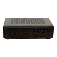
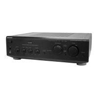
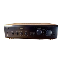
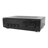
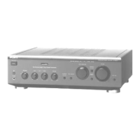
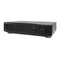
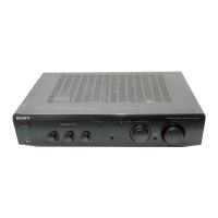
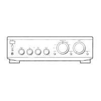
Details front and rear views of the amplifier controls and connections.
Procedure for disassembling the amplifier's outer case, including screw locations.
Procedure for disassembling the front panel assembly, noting connectors and clamps.
Steps for removing the main circuit board, indicating screw locations and connector disconnections.
Diagram showing the layout and location of various circuit boards within the unit.
Layout of the printed wiring board for the main section of the amplifier circuitry.
Detailed schematic diagram for the main section of the amplifier circuitry.
Layout of printed wiring boards for the panel sections of the amplifier.
Detailed schematic diagrams for the panel sections of the amplifier.
Layout of printed wiring boards for the power section of the amplifier.
Detailed schematic diagrams for the power section of the amplifier circuitry.
Detailed pin functions for Integrated Circuits used in the amplifier, including block diagrams.
Exploded view illustrating the parts of the amplifier's outer case, with part numbers.
Exploded view illustrating the parts of the amplifier's front panel section, with part numbers.
Exploded view illustrating the parts of the amplifier's chassis section, with part numbers.
Comprehensive list of components, including resistors, semiconductors, capacitors, connectors, and miscellaneous parts.