Do you have a question about the Sony TC-388-4 and is the answer not in the manual?
Explanation of the Panoramic Potentiometer's function.
How to operate the MUTING/PAUSE lever for tape control.
Visual representation of the unit's signal flow and architecture.
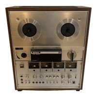
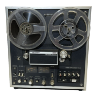
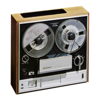
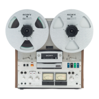
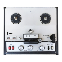
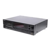
Identification of external controls and physical features.
Identification of internal components and circuit boards.
Procedure for removing the amplifier panel.
Steps for detaching the reel panel and head cover.
Procedure for removing the main external cabinet.
Procedures for mechanical tuning and calibration of the tape deck.
Procedures for electrical tuning and calibration of audio circuits.
Detailed electrical circuit diagrams for all unit sections.
Diagrams showing component placement on circuit boards.
Diagrams illustrating signal levels at various points in the circuit.
Diagram showing external and front panel component layout.
Diagram showing reel table and mechanical part layout.
Diagram showing pause and idler mechanism component layout.
Diagram showing head assembly and pinch roller layout.
Diagram showing circuit boards, switches, and jacks layout.
List of part numbers for complete circuit boards.
List of transistors, diodes, and ICs with their part numbers.
List of capacitors with part numbers, values, and types.
List of coils with part numbers and types.
List of transformers with part numbers and specifications.
List of resistors with part numbers and values.
List of switches with part numbers and types.
List of input/output jacks with part numbers.
List of miscellaneous parts like connectors and fuses.
List of included accessories like reels, manuals, and cleaning kits.
List of screws with part numbers and types.
List of washers with part numbers and sizes.
List of retaining rings (E-washers) with part numbers.
Explanation of screw types and hardware identification.
| Signal-to-Noise Ratio | 55dB |
|---|---|
| Reel Size | 7-inch |
| Tape Speed | 3.75 / 7.5 ips |
| Heads | 3 |
| Frequency Response | 30Hz to 22kHz at 7½ ips |
| Inputs | Line, Microphone |
| Outputs | Line output, headphone output |
| Semiconductors | Transistors, Diodes |
| Output | 0.775V |
| Type | 4-track reel-to-reel tape deck |