Do you have a question about the Sony TC-766-2 and is the answer not in the manual?
Critical safety warning regarding specific components identified by shading.
System control block diagram illustrating operational flow.
Block diagram detailing the amplifier section circuits.
Important notes and guidelines for performing repairs.
Procedures for mechanical adjustments and calibrations.
Procedures for electrical adjustments and calibrations.
Technical specifications for the RM-30 remote control.
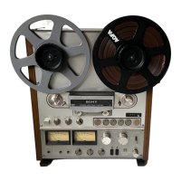
| Track System | 4-track, 2-channel stereo |
|---|---|
| Heads | 3 (erase, record, playback) |
| Reel Size | 7-inch |
| Tape Speeds | 3.75 and 7.5 ips |
| Frequency Response | 30 Hz to 20 kHz |
| Signal-to-Noise Ratio | 60dB |
| Inputs | Line In, Microphone In |
| Outputs | Line, Headphone |