Do you have a question about the Sony TC-755A and is the answer not in the manual?
Overview of the tape recorder's functional blocks and signal paths.
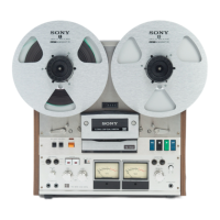
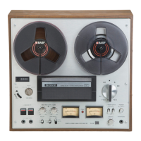
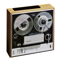
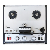
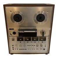
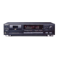
Identification and labeling of external controls, connectors, and indicators on the unit.
Illustration of the internal layout, highlighting major components and circuit boards.
Further illustration of internal component layout, focusing on specific mechanical parts.
Detailed view of the head assembly and pinch roller mechanisms.
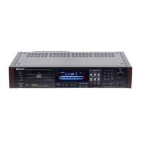
View of the front panel components and tape path guides.
Important operational guidelines, tape threading, and switch settings for optimal performance.
Precautions and guidelines for disassembly and tape height adjustment during repair.
Procedures for adjusting brakes, pinch rollers, and other mechanical components.
Procedures for calibrating electrical parameters like tape speed, meter levels, and head outputs.
Detailed schematic of the amplifier circuits within the tape recorder.
Diagram showing the physical layout of components on the amplifier circuit board.
Diagram illustrating the physical arrangement of components on the system control circuit board.
Detailed schematic of the system control circuits, including switches and solenoids.
Exploded view illustrating the assembly of the front panel and upper chassis components.
Exploded view showing the brake mechanism, solenoids, and related parts.
Exploded view detailing the tension arm assembly and associated components.
Exploded view illustrating the head assembly, tape guides, and pinch roller mechanisms.
Exploded view showing the pause and function switch mechanisms.
Exploded view detailing the function button assembly and lamp holders.
Exploded view of the motor and transformer assemblies.
Exploded view showing circuit boards, power supply components, and connectors.
Exploded view illustrating the amplifier section, including variable resistors and jacks.
Exploded view showing bias oscillator components, variable coils, and switches.
Lists complete and printed circuit boards with their part numbers.
Details transistors, ICs, and diodes with part numbers.
Lists capacitors, coils, transformers, thermistors, and resistors by part number.
Lists all switches, slide switches, rotary switches, and audio jacks.
Lists heads, fuses, meters, cables, and other accessories.
| Track System / Configuration | 4-track, 2-channel stereo |
|---|---|
| Channels | 2 |
| Tape Speed | 7.5 ips / 3.75 ips |
| Frequency Response | 20 Hz to 20 kHz |
| Signal-to-Noise Ratio | 60 dB |
| Output | Line Out |
| Inputs | Line In, Mic In |
| Heads | 3 (erase, record, playback) |