Outputs
0.5
Vataload
impedance
of
47
k
ohms
Load
impedance
|
Over
10
k
ohms
Output
level
1
mW
ata
load
impedance
of
32
ohms
Line
outputs
(phono
jacks)
Rated
output
level
Headphones
(stereo
phone
jack)
General
Power
requirements
US,
Canadian
model
:
120V
AC,
60Hz
AEP,
German,
East
European
model
:
220-230V
AC, 50/60Hz
UK
model
:
240V
AC,
50Hz
E
model
:
120,
220
or
240V
AC
adjustable,
50/60Hz
Australian
model
:
240V
AC,
50/60Hz
19W
Approx.
430
x
123
x
305
mm
(w/h/d)
(17
x
47/s
x
12
1/8
inches)
including
projecting
parts
and
controls
Approx.
4.0
kg
(8
Ibs
14
oz)
Power
consumption
Dimensions
Mass
Supplied
accessories
Audio
connecting
cords
(2)
Optional
accessories
Wireless
remote
commander
RM-J902
Design
and
specifications
are
subject
to
change
without
notice.
MODEL
IDENTIFICATION
(Specification
Label)
SONY:
TABLE
OF
CONTENTS
Section
Title
Page
Specifications
oC
ECP eEP
ee
Vere
eT
eee
eee
ee
Pe
Pee
eee
eee
ee
Cee
eee
Cee
eee
ee
ee
er)
l
Safety
Check-out
Perrrrrrrrrrrrrrrrrrr
rr
rrr
errr
ere
rere
rere
eee
ree
reer
eee
rey
3
1.
GENERAL
Identifying
the
Parts
on
the
Front
Panel
-+----+-+-
Pee
emnc
nas
ents
4
2.
DISASSEMBLY
2-1.
Front
Panel
Perr
rrrrrrr
rrr
err
rrr
errr
rere
errr
rrr
er
ree
re
eee eee
eee
5
2-2.
Mechanism
Deck
one
pia\a
el
piGid
bea
wcaliostearachiavas
S'S
8:
igs
aie
eine
Aree10.0
Ken's
a/ele/ele-i
5
2-3.
Audio
board,
Reel
RATE
tins
teie
teen
Seva
slee
ons
aedoned
awa
ta
6
2-4.
Head
(A),
(B)
Assy,
Pinch
Rollerceessrrccrerteterceeseeeeeens
6
3.
ADJUSTMENTS
3-1.
Mechanical
Adjustments
TORE
PECECEC
ESTEE
Se
eee
eee
eee
eee
7
3.2,
Electrical
Adjustments
VERT
TORT
T
STE
TE
eT
eT
eee
Te
Cee
ee
oy
4.
EXPLANATION
OF
IC
TERMINALS
--+-+-+----sseeeeeeee
11
5.
DIAGRAMS
5-1.
Block
Diagram
TEPEETURUTTUTTERETEREPTEEEE
EEE
OR
TES
ES
TEE
TO
T
Te
13
5-2.
Circuit
Board
Location
s:cstrrcrtsreeteeeesees
Gena
oslee
ues
uwes
15
5-3,
Printed
Wiring
Boards
PoCEESETYE
RCRA
COTE
COCOOe
Rc
16
5-4,
Schematic
Diagram
(System
control
Section)
-+++++++++
21
5-5.
Schematic
Diagram
(Audio
Section)
trrrrvtrrrrerrrerteees
26
6.
EXPLODED
VIEWS
6-1,
Chassis
Section
«srererssesssarcesscevsesssscsacceteenseseaneces
30
6-2.
Front
Panel
Section
srrrssrscsresrscesesersesesereesseceesens
3]
7
_
ELECTRICAL
PARTS
LIST
cecccecccrecteetceeeeeeenseeneeeees
a
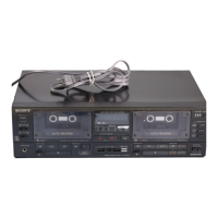
MODEL
NO.
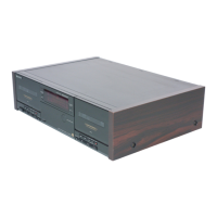
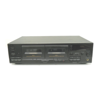
TC-WR445
STEREO
CASSETTE
DECK
Wlléhhhhhthhtttttthtttttttbl
US,
Canadian
model
UK
model
:
Australian
model
AEP,
German,
East
European
model
E
model
:
ne
:
AC
120V 60HZ
AC
240V
50Hz
:
AC
240V~50/60Hz
:
AC
220-230V~50/60Hz
AC120,
220,
240V~50/60Hz
 Loading...