EasyManua.ls Logo

Sony TC-WR445 Service Manual

Sony TC-WR445
32 pages
To Next Page IconTo Next Page
Page #1 background imageLoading...
Page #1 background image
_
TC-WR445
SERVICE
MANUAL
SPECIFICATIONS
4-track
2-channel
stereo
Approx.
150
sec.
(with
Sony
C-60
cassette)
Bias
AC
bias
Recording
system
Fast
winding
time
Signal-to-noise
ratio
(at
peak
level
and
weighted)
Type
IV
Type
II
Type
I
58
dB
57
dB
55
dB
S/N
ratio
improved
(approximate
values)
with
Dolby
B
NR
on:
5
dB
at
1
kHz;
10
dB
at
5
kHz
with
Dolby
C
NR
on:
15
dB
at
500
Hz;
20
dB
at
1
kHz
Harmonic
distortion
0.4%
(with
Sony
Type
I,
160
nWb/m,
315
Hz,
3rd
H.D.)
1.8%
(with
Sony
Type
IV,
250
nWb/m,
315
Hz,
3rd
H.D.)
Frequency
response
(Dolby
NR
OFF)
Type
IV
Type
II
Type
I
cassette
cassette
"cassette
TC-
30
-
18,000
Hz
|30-
17,000
Hz
|30
-
15,000
Hz
(+3
dB,
IEC)
(+3
dB,
IEC)
(+3
dB,
IEC)
30
-
13,000
Hz
[+3
dB
(-4
dB)
recording]
Model
Name
Using
Similar
Mechanism
Tape
Transport
Machanism
Type
US
Model
Canadian
Model
AEP
Model!
UK
Model
E
Model
Australian
Model
DECK
A
TCM-220WR1
DECK
B
Type
IV:Sony
Type
IV
(METAL)
Type
II:
Sony
Type
II
(HIGH)
Type
I:
Sony
Type
I
(NORMAL)
+0.15%
W.Peak
(IEC)
0.1%
W.RMS
(NAB)
+0.2%
W.Peak
(DIN)
Wow
and
flutter
Inputs
(phono
jacks)
Inputimpedance
|
47
k
ohms
Continued
on
page
2
*
Dolby
noise
reduction
and
HX
Pro
headroom
extension
manufactured
under
license
from
Dolby
Laboratories
Licensing
Corporation.
HX
Pro
originated
by
Bang
&
Olufsen.
“DOLBY”,
the
double-D
symbol
00
and
“HX
PRO”
are
trademarks
of
Dolby
Laboratories
Licensing
Corporation.
STEREO
CASSETTE
DECK
SONY.

Other manuals for Sony TC-WR445

Question and Answer IconNeed help?

Do you have a question about the Sony TC-WR445 and is the answer not in the manual?

Sony TC-WR445 Specifications

General IconGeneral
BrandSony
ModelTC-WR445
CategoryCassette Player
LanguageEnglish

Summary

Specifications

Signal-to-Noise Ratio

Details the signal-to-noise ratio performance for different tape types and Dolby NR settings.

Harmonic Distortion

Specifies the harmonic distortion levels for various tape types and recording conditions.

Frequency Response

Outlines the frequency response range for different tape types with Dolby NR OFF.

Input Specifications

Lists input signal levels and impedance for line inputs.

General Information

Power and Physical Specifications

Covers power requirements, consumption, dimensions, and mass of the device.

Model Identification

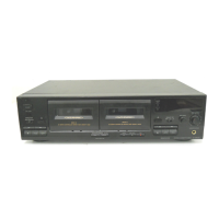
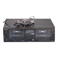
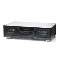
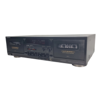
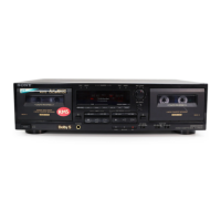
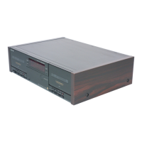
Provides information for identifying the specific model of the cassette deck.

Safety Checks

AC Leakage Test Procedure

Details the method for performing an AC leakage test on exposed metal parts.

Front Panel Controls

Control Identification

Identifies and describes the function of buttons and controls on the front panel.

Disassembly Procedures

Front Panel and Voltage Selector Removal

Step-by-step guide for removing the front panel and voltage selector.

Mechanism Deck Removal

Procedure for safely removing the mechanism deck from the unit.

Audio Board and Motor Removal

Instructions for removing the audio board and reel motor.

Head Assembly Removal

Details on how to remove the head assembly.

Adjustments

Mechanical Adjustments

Procedures for mechanical adjustments including cleaning and demagnetizing.

Record/Playback Head Azimuth Adjustment

Instructions for adjusting the record/playback head azimuth for optimal sound.

Playback Level Adjustment

Guidance on adjusting playback levels for both channels for optimal output.

Tape Speed Adjustment

Steps for adjusting the tape playback speed to specified tolerances.

Electrical Adjustments (Bias & Level)

Bias Consumption Current Adjustment

Procedure for adjusting bias consumption current when replacing key components.

Record Level Adjustment

Steps for setting and adjusting the record level control for optimal recording.

Record Bias Adjustment

Instructions for adjusting the record bias for optimal recording performance.

IC Terminal Explanations

Overview of IC Terminals

Provides a general overview and description of IC terminals used in the device.

IC Terminal Details

IC Pin Descriptions

Detailed descriptions of pin functions for specific ICs used in the system.

Diagrams

Block Diagram

Illustrates the overall functional block diagram of the cassette deck's circuitry.

Circuit Board Layouts

Circuit Board Locations

Diagrams showing the physical locations of various circuit boards within the unit.

Printed Wiring Board Layouts

Printed Wiring Board Layouts

Detailed layouts of the printed wiring boards for component identification.

IC Block Diagrams

IC Block Diagrams

Illustrates the internal block diagrams for key integrated circuits.

Exploded Views - Chassis Section

Chassis Section Parts

Diagram showing exploded view of the chassis section and its components.

Exploded Views - Front Panel Section

Front Panel Section Parts

Diagram displaying the exploded view of the front panel section parts.

Electrical Parts List - Audio

Audio Components List

List of electrical parts and their corresponding part numbers for the audio section.

Electrical Parts List - System Control

System Control Components List

List of electrical parts and their part numbers for the system control section.

Hardware List

Hardware List

List of screws, hardware, and fasteners used in the assembly.

Exploded Views - Mechanism Section 1

Mechanism Section 1 Parts

Diagram showing the exploded view of the mechanism section 1 components.

Exploded Views - Mechanism Section 2

Mechanism Section 2 Parts

Diagram showing the exploded view of the mechanism section 2 components.